1

enter image description here

I bought a Shimano hub dynamo that gives a maximum of 6 V with a regulator that they have provided. From what others here have said, the regulator is a Zener diode.

The output voltage of the dynamo increases with speed at which the bicycle is driven. 6V is only at around 10 km/h. By using the regulator, is all the energy being generated when I ride at greater than 10 km/h being burnt in the regulator? Isn't this a very wasteful way of dealing with the higher voltage?

Is there a more efficient way to deal with this?

PS. I've added a picture of the regulator that was with the dynamo. If this is not used, the voltage rises linearly with speed. When it is used the voltage only rose to 8-9V.

JRE
  • 67,678
  • 8
  • 104
  • 179
MikePainter
  • 11
  • 1
  • 4

4 Answers4

1

What is commercially called a hub dynamo is more accurately described as a magneto, or even more accurately as a permanent magnet synchronous machine.

The terminal voltage of a magneto is related to the change in magnetic flux linked through the coil by

$$v = -N\frac{d\phi}{dt}$$

The flux linking the magneto coil is made up of two components. One component is the flux induced by the permanent magnet linking the coil. The other component is the flux induced by current flowing through the coil. All of the flux induced by current through the coil also links the coil. We will call the linked flux induced by the permanent magnet \$m(t)\$. The flux induced by the current \$i\$ is proportional to \$i\$, so call it \$ki\$. Then,

$$\phi = m(t) + ki$$

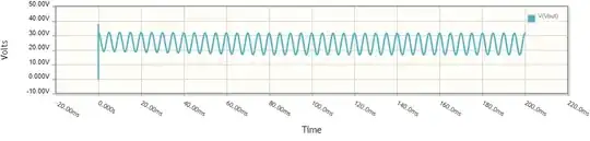
If the coil is open, and no current is flowing, the only flux component is from the permanent magnet. The faster the magnet (or magnets) rotate, the higher the rate of change of flux and the higher the open circuit voltage. This video shows the open circuit voltage generated by a hub dynamo increasing linearly to 100v (corresponding to a bicycle velocity of about 100km).

Automotive (and bicycle) synchronous machines are often regulated with shunt regulators. A Zener diode can be used as a simple shunt regulator, but it needs to have sufficient power rating. More complex shunt regulators often use power transistors. We will be especially interested to know how much extra power is dissipated by a shunt regulator when the speed of the magneto is increased.

If the voltage across the magneto's terminals is held to \$v_{max}\$ then the the rate of change of flux is given by

$$\phi' = -\frac{v_{max}}{N}$$

Integrating, we have

$$\phi = -\frac{1}{N}v_{max}t + C$$

So we have

$$-\frac{1}{N}v_{max}t + C = m(t) + ki$$

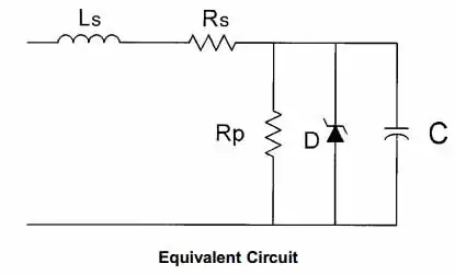
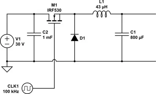
We can visualize this result by performing a simulation. We note that the shape of the flux wave induced by the permanent magnet(s) gets scaled on the time axis as the rotor speed increases, but is unchanged on the amplitude axis. This is similar to the effect of applying a constant rms amplitude alternating current to the primary of a transformer. Thus our simulation model can be something like this:

schematic

simulate this circuit – Schematic created using CircuitLab

The following diagrams show the open-circuit output voltage with the Zener diode D3 REMOVED, at an input frequency of 10Hz, 100Hz, and 1000Hz.

10Hz No Zener 100Hz No Zener 1000Hz No Zener

Those diagrams show the unregulated voltage increasing linearly with frequency, to a very high voltage of approximately 300V!

Next, here is what happens when a shunt regulator is present (in this case a 6V Zener diode). First at 100Hz.

100Hz 6V Zener 100Hz 6V Zener current

Notice that the output voltage remains near 6V and the current oscillates with a peak of around 200 mA.

Now comes the perhaps surprising result at 1000Hz.

1000Hz 6V Zener 1000Hz 6V Zener current

Once again, the voltage is about 6V and the peak current is about 200mA.

Thus, what we see is this.

  • When there is no shunt regulator present, the terminal voltage will increase linearly with the rotor speed.
  • The output voltage may be held constant by using a shunt regulator
  • When the output voltage is held constant by using a shunt voltage regulator, and the rotor speed is sufficient, the magneto current becomes independent of rotor speed (or at least approximately so).

From what others here have said the regulator is a Zener diode.

It might be, if the Zener is rated sufficiently to handle the maximum rated current of the magneto (hub dynamo) at the rated voltage. Otherwise, the regulator may be a shunt regulator employing a power transistor.

by using the regulator is all the energy being generated when I ride at greater than 10 km/h being burnt in the regulator. Isn't this a very wasteful way of dealing with the higher voltage.

As seen above, although the unregulated voltage increases with speed, the magneto's terminal voltage may be regulated with a shunt regulator. When regulated with a shunt regulator, there is a maximum electrical power that will be generated, regardless of rotor speed. Some of that power may be dissipated by a light or other device. The excess power (i.e. the relatively fixed power generated minus the power used by devices) will be dissipated by the shunt regulator.

Math Keeps Me Busy
  • 18,947
  • 3
  • 19
  • 65
  • 2
    You are missing the large leakage inductance that is effectively in series with the output. Much of the voltage drop when the shunt regulator is active is dropped across that inductance. The energy is stored and not lost. It is returned to the source (ie mechanical input) later in the cycle. – Kevin White Aug 14 '21 at 20:42
  • I did not include eddy current, hysteresis or copper losses either. Because to understand why a 6V zener can be connected across the terminals of a magneto that can otherwise generate hundreds of volts the model I gave is sufficient. There is flux linking the coils. The rate of change of that flux is proportional to the to terminal voltage. The total flux linking the coils is equal to the flux induced by the permanent magnets that links the coils plus (algebraically) the flux induced by the current through the coils. Doesn't that include the flux in your "leakage inductance"? – Math Keeps Me Busy Aug 14 '21 at 21:19
  • most of those terms are unimportant but in your equivalent circuit the leakage inductance is an import component or you have a voltage source directly feeding the Zener diode. The linkage of the flux does not include the leakage inductance. You can also represent it by reducing the coupling coefficient of the transformer to less than unity, you imply an ideal transformer. – Kevin White Aug 14 '21 at 21:27
  • @KevinWhite no, there is no voltage source directly feeding the Zener. Your claim that the linkage of the flux does not include leakage inductance makes no sense. (Self) Inductance, leakage or otherwise does not exist apart from flux generated by current through a coil, and a related emf proportional to the rate of change of flux. Don't need to reduce coupling co-efficient. You can add inductance on the primary side of the transformer in the model and it will have exactly zero effect, because the primary is fed by a current source. – Math Keeps Me Busy Aug 14 '21 at 21:33
  • I agree, my error. I missed that the energy source in your example was a current source. – Kevin White Aug 14 '21 at 22:31
1

The zener is likely in case there is no other load connected. It doesn't waste much power in normal operation.

A bicycle dynamo is a voltage generator (as explained in some of the previous answers) in series with a significant inductance (from leakage of the coil). As the dynamo spins faster, the frequency of the AC generates also increase, and so does the impedance of the inductance. If the output was shorted, you would find a nearly constant (AC) current flowing, independent of speed.

A load (such as a light bulb) acts as a low impedance load, and therefore receives a nearly constant current from the dynamo at any speed.

The inductance does not dissipate power, so doesn't waste any.

jp314
  • 18,395
  • 17
  • 46
0

Generators are current sources, you're not wasting much energy because the available current is limited by the strength of the magnet.

  • That is not generally true. Moving a wire through a magnetic field generates a voltage, not a current. Many alternators (such as this one) have large leakage inductances and so they act as a variable voltage/frequency source in series with an inductor that gives it the behaviour of a current source. – Kevin White Aug 13 '21 at 00:00
  • The norton equivalent to your thevenin circuit is simpler, fixed current variable frequency source. with parallel inductor. – Jasen Слава Україні Aug 13 '21 at 00:11
  • @KevinWhite please be aware that the relationship between terminal voltage and rate of change of flux can work either way. If the rate of change of flux is fixed, then the terminal voltage will depend upon it. However, if the terminal voltage is fixed, the rate of change of flux will depend upon that. In a magneto with a shunt voltage regulator, the fixed terminal voltage determines the rate of change of flux. – Math Keeps Me Busy Aug 14 '21 at 21:27
0

If there are no other components on the rear of the board (which seems like to be the case) that will be a simple clamp regulator using zener diodes.

An indication of the power available can be gained by disabling the regulator (remove two diodes or two resistors) and operating the dynamo into a load at speed. A small light bulb or few or resistors would work.

The ideal solution would be an XXX volt to 5 v buck converter.

Russell McMahon
  • 147,325
  • 18
  • 210
  • 386