What is the difference between a diode rectifier and an op-amp diode (precision) rectifier? What is the need for an op-amp in the second case? Thanks for the easy explanation.
Asked
Active
Viewed 408 times
2
-
4I think you mean "precision rectifier" by "op amp rectifier". They have nearly zero voltage drop *(i.e. output peak voltage is equal to the input peak voltage)* unlike the diode-rectifiers. – Rohat Kılıç May 03 '20 at 03:34
-
1I've edited the body of the question to make it clearer and am currently preparing a comprehensive answer. So there is reason to reopen the question. – Circuit fantasist Aug 07 '23 at 12:34
6 Answers
5
Let's look at a simple full-wave implementation:

courtesy of https://www.analogictips.com/how-does-a-precision-rectifier-work-faq/.
A full bridge could approximate this behavior, but there would be gaps when the response nears one diode drop from zero due to the non-ideal source of the diode...the output bumps would be ~0.7V shorter (for silicon diodes), peaking at ~2.8V, and have flat spots at 0V due to the diode drops.
This circuit emulates an ideal bridge rectifier with no drop. This is done in two parts: When the input cycle is positive, it drives the output of the first op amp low, causing the diode to be reverse biased. As such, the input directly drives the buffer through 400K, a small resistance compared to the input bias current of the second buffer op amp. The resulting output is identical to the input.
When the input goes low, it drives the output high in order to compensate. The output must go high enough so that the positive voltage at pin 5 is the exact inverse of the negative input. Because the feedback resistor comes after the diode, the output at pin 1 must compensate for the diode drop so that the feedback condition is satisfied. The result is that during that part of the cycle, the output is the exact inverse of the input. You essentially have a full wave bridge without the distortion of the diode drops.
Note that this is useful only for signals. While it might be tempting at first glance to use it for power efficiency, that application falls apart in two ways:
- the output is limited to the voltage and current the op amp can supply, and
- the power coming from the output is not derived from the input, but from the op amp supply.
It is as such limited to signal applications where precise measurement is important and power transfer is not needed.
Cristobol Polychronopolis
- 9,622
- 9
- 17
-
This is a very interesting and even paradoxical circuit solution. I was deeply impressed when I first met it and had to [explain](https://electronics.stackexchange.com/a/645466/61398) what the idea behind it was. – Circuit fantasist Aug 09 '23 at 14:29
2
Explaining by "inventing"
To reveal what the op-amp does in the circuit of the precision diode rectifier, I will use, contrary to the textbook formal "explanations", an unconventional path to the truth - by reinventing the circuit. My reasoning for this is that op-amp diode rectifier circuits are somehow improved diode circuits, and to understand them we need to uncover how this "magic" is done. The best way is to first break down the circuit into simple functional blocks and then start assembling it following the basic idea.
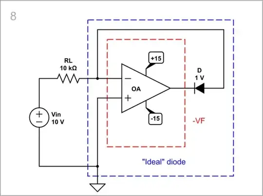
"Ideal" diode rectifier
When connecting an "ideal" diode D (with zero forward-voltage VF) in series to the AC input voltage source Vin to make the simplest series diode rectifier, during the positive half-wave of the input voltage, we observe the same voltage across the load RL. There is no voltage drop across the diode; it acts just as a "piece of wire".
simulate this circuit – Schematic created using CircuitLab
The two graphs - of Vin and VRL, are the same during the positive input half-wave.

Main problem
The main disadvantage of Si diodes is the forward-voltage drop VF across them. It is approximately 0.7 V but for convenience, in the conceptual CircuitLab schematics below, I have assumed it is 1 V. My reasoning for this is that when we consider fundamental ideas, the exact values do not matter and it is fine to round them to whole decimal numbers (they are also a favorite of the simulator). The same applies to the specific designations and parameters of the devices, which is why I deleted them.
Real diode rectifier
So, when connecting a real diode in series to the AC input voltage source to make the simplest series diode rectifier, 1 V is lost and the voltage across the load RL is decreased with 1 V. This voltage loss (drop) is similar to that across a resistor but with a relatively constant value. We can imagine the diode as a "dynamic resistor" that decreases its resistance R when the current I increases and vice versa so that their product V = I*R remains relatively constant.
As a result, the graph of the output voltage across the load in the DC sweep simulation below, is shifted down by the voltage VF = 1 V.

Basic idea
The remedy is obvious and well known to us from life - as there is a voltage loss (drop) VF, we must add the same amount of voltage to compensate for it. Thus, it will help the imperfect diode with VF = 1 V that will become "ideal" with zero VF.
Implementation
The idea is fine... but how to implement it in practice?
Increased input voltage
The simplest way would be to somehow increase the input voltage with VF (1 V).
Conceptual circuit: Since I could not figure out a better way to do it in CircuitLab, I just connected a VF voltage source in series with the input source and surrounded them with a dotted line to show that this is actually a "Vin + VF" (increased with VF) voltage source.
The result is fascinating - since the graph of the input voltage is "lifted" by 1 V, the graph of the output voltage matches the initial Vin graph.

Negative-feedback conceptual circuit: The above circuit is not precise, because the forward voltage VF of real diodes is not strictly constant but slightly varies when the current changes. So let's apply a clever trick known as a "negative feedback principle" in the form of a fun "game". For this purpose, supply the load by another varying voltage source VOA and connect a null indicator NI (sensitive voltmeter) between the input voltage source Vin and the load. Then, looking at NI, adjust VOA until NI's reading becomes zero. The result is amazing - VRL exactly follows Vin!
Op-amp circuit: An op-amp OA can do this boring work. Now it produces the voltage VOA and adjusts it to make VL = Vin. The circuit can be considered as an op-amp follower that is disturbed 1 V by the diode D. In an effort to compensate for this disturbance, the op-amp "lifts" its output voltage before the diode by 1 V so the voltage VL after the diode is exactly Vin.
It is unfortunate that during the negative half-wave of the input voltage the op-amp is left with no feedback and saturates but this is beyond the object of our consideration.

Added VF voltage
Instead of increasing the input voltage by VF, the latter can be added, according to KVL, through a separate voltage source VF in series. But where do we insert it?
Note that in the loop of four devices (Vin, D, VF abd RL), only two of them can be grounded. One of the grounded devices must surely be the input voltage source; it remains for us to decide what the other will be.
Floating VF voltage source, grounded load: Although possible, this configuration is difficult to implement because in circuits, signal voltage sources are typically grounded (their voltage is a derivative of the power supply which, as a rule, is grounded).
You can see in the graphs below that the problem is still solved.

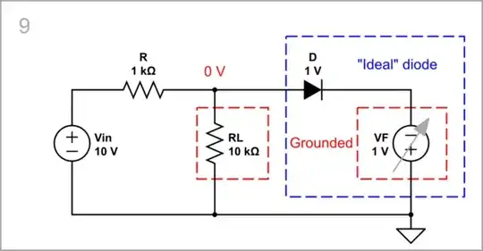
Grounded VF voltage source, floating load:
Conceptual circuit: If this is possible, we can leave the load floating and the VF voltage source grounded. However, something interesting happens here - VF must be negative with respect to ground in order for its voltage to be added to the input voltage. Note that the midpoint between RL and D has zero voltage. Let's see it in our fun "negative-feedback game". Now connect the null indicator NI between the midpoint and ground. Then, looking at NI, adjust VF until NI's reading becomes zero. The result is amazing - VRL exactly follows Vin!

Op-amp circuit: It looks a bit weird but works (I am not giving a 100% guarantee though because the idea came to me today:-) Hmm... this circuit is not so bad because the load is still grounded... but virtually on the right side. Aha... this is the famous "virtual ground"! So Vin and VF are truly grounded and RL is virtually grounded.
As above, there is a problem during the negative half-wave of the input voltage because the op-amp is left with no feedback and saturates.

Grounded VF voltage source, grounded load: In some applications (e.g., diode limiters), a grounded load is connected in parallel to the "ideal" diode (D + VF). So the load is shorted when the "ideal" diode is on and the voltage across it is zero. This is an example of a parallel op-amp diode rectifier.
Conceptual circuit: Things are reversed here - the input voltage is applied to the load during the negative half-wave.
Note, however, that this is only a part of the input voltage because a voltage divider R-RL is formed.

Op-amp circuit: In the op-amp implementation, the op-amp produces only the compensating voltage -VF.

Summary
- The main problem of pure diode rectifiers is the forward-voltage drop VF of diodes.
- It can be compensated by increasing the input voltage Vin with VF; this results in a non-inverting configuration.
- It can be also compensated by adding the same voltage VF to the input voltage Vin; this results in an inverting configuration.
- For this purpose, an additional voltage source VF can be connected in series so four devices - Vin, D, VF and RL are connected in a loop.
- The two sources are of opposite polarity with respect to the ground, but with the same polarity when traveling along the loop, which is why their voltages add up.
- The compensating source VF can be implemented by a properly supplied op-amp.
- The op-amp diode rectifiers thus created are perfect but can only be used in low-current applications due to the small op-amp output current.
Circuit fantasist
- 13,593
- 1
- 17
- 48
1
A diode rectifier is, in the simplest case, a single component that, in simple terms, allows current to flow in one direction and not the other. An op-amp rectifier is a more complex circuit whose function is to rectify an input signal and output the resulting voltage.
Frog
- 6,686
- 1
- 8
- 12
0
Circuit fantasist provided a complete, comprehensive answer which was probably far more than you wanted digest. David Andrea provided the ultimate short and snappy answer which completely lacks details. Let me try for something in between.
The best way I can start is to ask, "What would someone want to rectify a voltage/signal for?". There are basically two classes of answer: to convert AC power voltage to DC voltage to provide power, or to use a rectified AC signal in a circuit which does pretty much anything else.
Converting AC to DC for power use has a couple of characteristics. Typically you need high current, say something over 100 mA. It's OK to drop voltage during the conversion, as long as it doesn't drop much. Call it 1 volt for a typical system. For these applications, using a rectifier diode is the standard approach. You take (typically line) AC in, use a single cheap diode or 4 for a bridge, and you get DC out. Depending on your diode you can deal in hundreds of volts and hundreds of amps. Easy peasy. OK, you then have to filter the rectified AC, but you get the idea.
If, instead, you want to do something like measure an AC voltage, a rectifier can really suck. Diodes don't rectify accurately down below about 1 volt, so measurement at low voltages is not a good idea. Diodes have leakage currents which can vary wildly with temperature, which is also .. unfortunate.
In this case, a precision rectifier is just the thing. It uses the gain of the op amp to overcome the effects of diode nonlinearity, and produces a, well, precise rectification. And if temperature is an issue, you can use differential techniques to to provide at least first-order compensation using another diode.
Of course, it sucks at providing power. Let's say you want to provide 24 volts at 10 amps. A rectifier should be something like 50 volts at 20 amps just to be safe, but those are cheap. A precision rectifier needs a couple of op amps which can put out 24 volts at 10 amps, and you won't get one of those puppies off the shelf. Not only that, op amps aren't normally built with power efficiency in mind, so efficiency will likely be horrible. You CAN work around this with custom circuitry, but this is left as an exercise for the reader.
Of course, there are exceptions - there always are. Some signal functions, such as detection/demodulation of RF signals, are easily carried out by diodes acting as (sort of) rectifiers. And for very high-effidiency, high-power rectification, you might look up "synchronous rectification", which can use op amps/power MOSFETs.
WhatRoughBeast
- 59,978
- 2
- 37
- 97
-1
A diode rectifier can turn on very quickly (the silicon diode only needs about 0.026 volts, for the current to increase 2.7X, or about 0.06 volts for a 10X increase) and that rapid current transient causes interference in audio systems and precision measurement systems and in certain radios.
Thus some diode rectifiers, in power supplies crafted for low Magnetic Interference, have series inductors to slow down the current risetimes.
The opamp rectifier does not have this interference property.
analogsystemsrf
- 33,703
- 2
- 18
- 46
-
4
-
1You wouldn't use it for a power supply, because the output power is coming from the op amp supply rather than the input. – Cristobol Polychronopolis Aug 08 '23 at 16:27