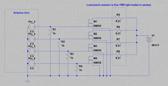
I am attempting to test discharge of a large battery pack. I am trying to set up an arduino that controls the discharge by using a bank of 75W bulbs. I have set up my system like shown in the picture. The issue is that the second I turned on the mosfets with the Arduino the first mosfet blew fairly quickly. In my mind this set up should work, but its oviously not...what am I doing wrong? I'm using some spare FQPF20N60 mosfets I had. From what I can tell the Vgs(th) on this mosfet is 5V and is well under the Vgs which is 10V.
Asked
Active
Viewed 35 times
0
-
If Vgs(th) is 5V an Arduino cannot drive them directly. You need to drive them with the Vgs at which the ON resistor is measured : you said 10V. At 5V they don't turn fully on; drop a lot of voltage across the FET, dissipate a lot of power, with the effect you observed. Also, duplicate of many other questions here. – Apr 29 '20 at 19:03
-
you my friend are a scholar and a priest, I was only finding things related to people paralleling the gate voltages to be able to control it with an arduino but not the other way around, this makes sense. – Dan Hernandez Apr 29 '20 at 19:12
-
Another factor is that the cold resistance of bulbs is very low - inrush current may be 10 x run current. Nichrome wire eg from an old heater or toaster has nearly constant resistance hot or cold. – Russell McMahon Apr 29 '20 at 20:45
-
interesting, what about placing an NTC thermistor inline to prevent inrush? – Dan Hernandez Apr 29 '20 at 22:17
-
@DanHernandez NTC -> You could, but if you want quantitative results from the test then a well defined load may be useful. Bulbs are OK. Nichome is probably better. It's availanble new. but there are many sources of old free Nichrome. If you have say a 1000 Watt 100 VAC element then to run some at 58V at the same load per length you want about 58/110 of a length. Annoying that it's not 50% so you can double it. || BUT as P = V^2/R - using a say 1000 watt element at 58V means power will be (58/110) ^2 x 1000 = 278 Watts. ... – Russell McMahon May 02 '20 at 01:02
-
... It looks like you want 5 x 75W x 4 = 1500 Watts. |2 x 1 kW 110 VAC elements trimmed to part length in parallel should suffice. You can use mechanical tapping with a clamp. – Russell McMahon May 02 '20 at 01:02
-
That looks like a 16S LiIon battery (58.8/16 = 3.675)(you should say). If so Vmax is 4.2 V / cell so 4.2 x 16 ~= 68V max and maybe around 50V min. [Lead acid 4S looks less likely (14.7 V/12V battery)]. | Say 60V. battery mean. So use 80% of a 1 kW element x 4. Parallel 2 x 80% lengths to give 750W at 60 VDC. Use two of these in parallel to give 1500 W at 60 VDC. Tapping onto uncut heater or toaster elements allows adjustment to suit. – Russell McMahon May 02 '20 at 01:59
1 Answers
0
You aren't applying enough gate voltage. See the \$I_d\$ vs \$V_{gs}\$ graph below from the datasheet. At 5V, you only have enough \$V_{gs}\$ to get about 1 Amp, which means the light bulbs only drop about 10 of the 59 Volts. So the MOSFET has 49 Volts across, at 1 Amp. So about 50 Watts of dissipation.
rpm2718
- 2,632
- 1
- 6
- 14

