10

I often see two zeners (in opposition to each other) being placed across the power supply rails. I don't understand why that is necessary.

For example, if I have a 16V Zener diode and a 12V power rail, the 16V Zener will protect the supply from transients above 16V. It will also prevent negative transients below -0.7V - say, if i reversed the battery.

Why would placing two zeners in opposition improve this. Say if I placed two 15V Zeners in the same setup. It will now protect the supply from transients above ~16V (which is fine). but it now will only protect the supply from negative transients below -16V instead of -0.7V. Why would anyone want this? I don't want the supply rail to go to the negative at any stage!

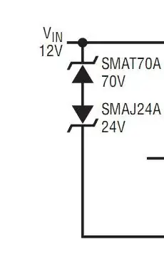
For example: see example circuits in http://cds.linear.com/docs/Datasheet/4359f.pdf

cksa361
  • 3,814
  • 7
  • 33
  • 49

2 Answers2

7

Automotive Design standards are very strict.

Electronics must survive a car being jump started in reverse and boosted with 24V. (Yes people still do that in dead of winter) It must also handle load dump with a battery under load being disconnected.

If your design shunts the battery at -0.7V it will blow like a fuse then you have no protection.

So be warned automotive tests are much stricter. This particular design of zener is to protect the regulator from failure within its abs. max input. of -40V ~+80V, which might seem enough but these zeners will not blow in the automotive +24/12V test yet protect the device from additional spikes above that.

enter image description here

Tony Stewart EE75
  • 1
  • 3
  • 54
  • 182
5

Bidirectional TVS devices, as you mentioned, have no polarity. They can be used to limit positive and negative swings in an AC application. Two unidirectional devices in series can do this as well, but you can tailor the clamping threshold by changing the TVSs - you could have a 12V in series with at 24V with opposite polarity, and the clamp would work at 12V + 0.6V one way, or 24V + 0.6V the other way.

In a DC circuit, they can be inserted either way and will 'work' as you described - a useful positive clamp, and a less-than-useful (in many cases) negative clamp. If you install a single unidirectional TVS backwards, however, you've got a really stiff positive clamp across what you're trying to protect - for your example, instead of 16V, it'll be stuck at 0.6 - 0.7V.

For low-voltage clamping (like ESD clamps on I2C lines), it's normal to go with the unidirectional devices to keep negative spikes in check.

Your cited datasheet shows an automotive application, where the DC coming from the battery / alternator is just about the nastiest DC source you could imagine (incredibly stiff and subject to immense, scary transients / surges etc.) - the choice of a 70V TVS in series with a 24V one is deliberate:

The LTC4359 operates from 4V to 80V and withstands
an absolute maximum range of –40V to 100V without
damage. In automotive applications the LTC4359 operates
through load dump, cold crank and two-battery jumps,
and it survives reverse battery connections while also
protecting the load.
Adam Lawrence
  • 32,921
  • 3
  • 58
  • 110