1

how are you?. I'm doing a project in Proteus whose I wanna do it as modular as possible, from the principal sheet I've an LCD screen (see the Image 1 and Image 2)

Image 1: Conexión a la pantalla LCD

and its terminals are been moved with bus cables to a subcircuit and inside the subcircuit I put another bus named as the terminal bus on the external part of the subcircuit, dimensioned to manage all the necessary signals.

Image 2: Puertos para buses en el subcircuito

Inside the subcircuit (se Image 3) all is connected but when I run the simulation the LCD terminals in the main sheet appears floating which means that the interconnection doesn't be made apparently by an error of mine, if I use normal terminals for one connection then the simulation works fine.
Image 3: Conexión dentro del subcircuito. How can I solve the problem with the bus cables.

Thanks in advance for the help.
vram
  • 158
  • 12

1 Answers1

1

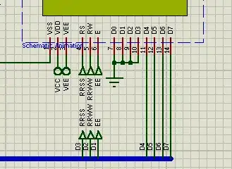
well, thanks to another friend I've noted that the names of the buses in the main sheet where different (LCD screen bus) to the names in the subcircuit, at the main sheet said LCD[1..7] and in the subcircuit sheet said LCD[1..3], other reason is that the wires named RS, RW and E proteus as far as I could read again in the help couldn't be transmitted to the main sheet in the way that the bus cable was drawed by me so I had to modify those names and put names on the taps of the bus cables. Attached are the pictures of how the circuit is working right now.

NOTE: The labels RRSS, RRWW and EE are simply visual aids to me.

Bus in the subcircuit.

Bus out of the subcircuit in the main sheet.

Bus entering the LCD display.

vram
  • 158
  • 12