There are plenty of possible sources for noise, and all of them are pretty much to be expected. Real circuits have to deal with reality, and reality has a lot of things that simulators often ignore.
Possible noise sources:
- The resistors. Passing a current through resistors causes noise to be generated in the resistors. Heck, they generate noise just by being warm.
- Power supply regulators aren't perfect, so the voltage can change with time. Since they also include resistors (and other parts that will generate noise,) the output of any voltage regulator will have noise.
- Received noise. There are many sources of electromagnetic disturbances. These can be received by the wires (and other components) in your circuit.
- Noise generated by your own circuit. If your circuit switches things on and off (or even just has an amplifier) then it will cause variations in the supply voltage. These will then get into your amplifier circuits and cause noise there.
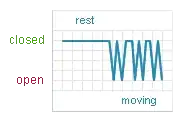
- Potentiometers. The wipers on potentiometers "scratch" along the resistance track. Mechanical motion will cause more noise. Even just sitting there, the wiper is under (physical) tension - it presses on the resistance track. That causes noise.
Noise is a fact of life in any electrical circuit.
Proper design can reduce it, but not eliminate it entirely.
- You can shield things to reduce noise picked up from the environment. That's shielded cables and metal enclosures for the circuit.
- You design so as to reduce noise. High value resistors generate more noise than low values, so you use low value resistors. How the wires (or traces on a printed circuit board) run influences how easily noise from one part of a circuit jumps to another part of the circuit.
- You use filters to reduce noise when it gets into your signals.
- You use components that them selves generate little noise. A power supply that generates hundreds of millivolts of noise will be a problem for a sensitive circuit. An amplifier that adds a lot of noise to your signal will be more of a problem than an amplifier with a lower noise level. The LM358 is a good(ish) opamp for general use, but probably far too noisy for the task you've set it.
The above lists of sources and cures don't even begin to cover all the possibilities. There are entire books about the subject.
Amplifying nanovolt level signals is not what I'd call a good first project.
Mmmpf.
Missed it the first time around: "changing breadboard."
A breadboard is the last thing I'd use when working with such small signals. Every wiggle of every wire is a noise source - even if the wiggle is too small to see. That'll easily generate millivolt level variations (and more) in your output.
Load cells them selves aren't exactly quiet.
This site has some information specifically about load cells and noise.
If I were building anything with a load cell, I'd probably use an ADC designed for load cell use. That's an example. There are many more out there. The 24 bit ADC takes care of sampling (measuring) the load cell voltage with low noise. It also filters the sampled data to reduce noise. You'll still have to pay attention to the layout and power sources, but at least you don't have to try to design a high gain, low noise instrumentation amplifier.
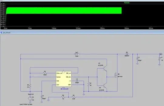
For an idea of what kind of noise you'll encounter at the signal levels you want to look at, here's few measurements I made with my oscilloscope and some random bits and pieces from my workbench:
Circuit:
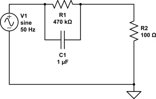
simulate this circuit – Schematic created using CircuitLab
Scope probes shorted:
That's about 40 microvolts peak to peak of noise with the scope probe shorted to its own ground clip. That's a reference for how far down my scope can work.
Noise voltage from a 9 volt battery:
That's a total of 80 microvolts peak to peak from the scope and the battery together.
Battery with a load of 102kohm:
That's around 350 microvolts peak to peak of noise, just by putting a very light load on the battery. I didn't get the bottom cursor set right, so add about 100 microvolts (1 division) to the measured value (264 microvolts) to get the correct value (~350 microvolts.)
Noise at the divider (from ground to the junction of the two resistors:)
That's 430 microvolts peak to peak across just one of the resistors.
Now for the best part - the divider with no battery. Just the resistors:
That's 4 millivolts (!) peak to peak of noise that the probes pluck from the environment when just the two resistors (102kohm) are connected to the probes.
Getting clean signals at such low levels is hard.
Commenter PNDA asked what happens if I change the temperature of the resistors for the last setup (just the resistors connected to the probe.)
Nothing measurable happens. Most of that noise comes from elsewhere.
I twiddled with the trigger on my scope, and found that most of the noise was at about 28kHz. With a proper trigger, I could also measure the RMS value of the voltage. It came out to about 2mV RMS. With the scope probes in parallel to the resistors, there's a load of about 97kohm. Total received power is about 0.041 microwatts.
The source of the 28kHz interference was the powersupply of GSM modem I have plugged into an outlet on my workbench.
With the GSM modem unplugged, the interference dropped to about 120 microvolts RMS into 97kohms. The frequency was also different - 80kHz. That's about 0.000145 microwatts of received power.
More investigation showed that the 80kHz interference comes from the power supply of the monitor I have on the workbench. The monitor is the display for the oscilloscope software I use, so I can't practically unplug it to make the noise go away. I could, however, move the scope probe with the resistors closer to the (back) of the monitor and make the interference stronger. That kind of proves the source.
Ultimately, both sources of interference were capacitively coupling into the electrostatic protection mat on the workbench, and from there capacitively coupled into the resistors and probe. Moving the probe away from the workbench surface would reduce the interference.
Like I said, microvolt level stuff is hard to get clean.


