2

I have come to read that reactive power is that power which is constantly oscillating between the source and the load.

Can anyone please explain this to me?

Suppose an AC source is connected with an inductor. The power is reactive in inductor as we know but how will oscillation of reactive power take place between the inductor and the source?

I need intuition on all this process?

JYelton
  • 32,302
  • 33
  • 134
  • 249
Alex
  • 1,018
  • 2
  • 12
  • 26
  • 1
    The Reactive power oscillating because the inductor for 1/4 of cycle stores the energy in the form of a magnetic field and during another of cycle part releases the stored energy back to the source. And we have a similar situation with the capacitor. During charging we "absorbing" power from the source and during discharging we releasing power back to the source. https://electronics.stackexchange.com/questions/287394/ac-circuit-having-only-capacitor/287475#287475 – G36 Apr 11 '20 at 12:13
  • 3
    Does this answer your question? [What exactly is reactive power, in concrete terms?](https://electronics.stackexchange.com/questions/488482/what-exactly-is-reactive-power-in-concrete-terms) – vu2nan Apr 11 '20 at 12:31
  • That case https://electronics.stackexchange.com/questions/488482/what-exactly-is-reactive-power-in-concrete-terms has also numeric rule which relates the calculated reactive power UI*sin(phi) and the actual energy flow from source to electric and magnetic fields of capacitors and inductors. This relation is systematically skipped in texbooks. –  Apr 11 '20 at 13:38

3 Answers3

3

The power is reactive in inductor as we know but how will oscillation of reactive power will take place between the inductor and the source?

Following on from your previous question, I have taken the picture and reduced it to focus on the relationship between voltage and current for a resistor (top) and a pure inductor (bottom): -

enter image description here

In the top diagram the power waveform (red) is wholly positive i.e. it never drops below the "zero" line (black). This means that power is never returned to the source i.e. it is all converted to heat.

In the lower diagram, current (blue) lags voltage (magenta) by 90 degrees and, the resulting power waveform (red) straddles the zero line perfectly. This means that power is put into the inductor during the time when current magnitude is rising and then, when current magnitude is falling, power is taken back (power is negative). Average power is zero.

Andy aka
  • 434,556
  • 28
  • 351
  • 777
  • "This means that power is put into the inductor during the time when current magnitude is rising and then, when current magnitude is falling, power is taken back (power is negative). Average power is zero." this reactive power is taken back by the source in the form of inductive kick by the inductor? @Andy aka? – Alex Apr 11 '20 at 12:08
  • @Alex correct.. – Andy aka Apr 11 '20 at 12:10
  • 1
    The positive power means that we are "absorbing" power from the source (circuit), the charging phase. Negative power means that the inductor is releasing power back to the source (circuit), discharging phase. – G36 Apr 11 '20 at 12:11
  • this reactive power is taken back by the source in the form of inductive kick by the inductor? @Andy aka? G36? – Alex Apr 11 '20 at 12:12
  • 3
    @Alex it's not a DC circuit so I wouldn't call it a kick. – Andy aka Apr 11 '20 at 12:13
2

In order for power to oscillate back and for the between the source and the inductor, the source must be capacitive. That is, it must either contain a capacitor of a sufficient size or it must be able to behave as if it were a capacitor. Wound field synchronous generators can be made to behave as if they were capacitors by adjusting the field current. Any other type of generator or AC source, requires a capacitor to supply an inductive load.

The key concept here is that energy is stored in capacitors and in inductors. Since the current leads the voltage in a capacitor and lags the voltage in an inductor, energy can "oscillate" or transfer back and forth between a capacitor and inductor. That should provide a decent intuitive understanding of the statement "Reactive power is that power which is constantly oscillating between the source and the load." This is mostly a concept that is important in AC power generation, transmission, distribution and utilization. It may be looked at differently in the signal world.

Note that it is also useful to understand the mathematics as presented in the time domain by @Andy aka. At some point, you will also need to understand the vector representations.

The understanding of how a wound-field synchronous machine can act as a capacitor is important, but beyond the scope of this question.

More Detail

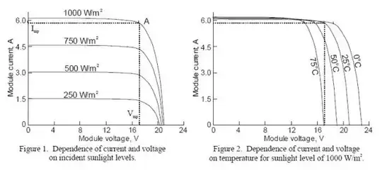
To look at the problem in more detail, refer to the diagram below.

At phase angle zero, the current is zero, so the inductor magnetic field is zero and no energy is stored. The applied voltage causes the current to rise and energy is transferred to the resulting magnetic field in the inductor. The rate of transfer of energy from the source to the load is shown by the power curve. The power at each instant in time is the voltage at that time multiplied by the current at that time. The actual energy stored is the area under the curve.

At 90 degrees, the voltage reverses, the current begins to decrease and energy is transferred from the inductor back to the source. The power is negative because the direction of energy transfer has reversed.

At 180 degrees, the current reverses resulting in another reversal of the direction of energy flow.

The flow of energy continues back and forth as shown.

If the AC source is considered to be ideal, we can simply say that it accepts the returned energy. A real power source must have a physical mechanism to accept the returned energy. It has been proposed in a comment that the generator simply asks as a motor and accelerates its own inertia and the inertia if the driving engine slightly every time it received returned energy. That might be possible, but at minimum, it is problematic and inefficient. What happens in power distribution systems is that capacitance is built into the source to complement the load inductance by storing energy the times the load returns it and supplying it back to the load as needed. As mentioned above, the capacitance may be supplied by a capacitor or by using the unique capability of a synchronous machine to "behave as a capacitor."

Note that the vertical scale in the diagram is 100 V, 100 A and 1000 W per division.
enter image description here

  • Ok so if we have both inductor and capacitor in the circuit with ac voltage source then how will this oscillation of power take place? – Alex Apr 11 '20 at 11:55
  • That is a good question. Since electric power suppliers incur some cost in allowing loads to transfer power back and forth, they incentivize large customers to supply their own capacitors for their induction motors. They are called power factor correction or compensation capacitors. Adding a capacitor at the load allows power to oscillate back and forth locally. It is really energy that transfers back and forth. Power is the measurement of the rate of energy transfer. –  Apr 11 '20 at 12:02
  • I agree that saying the source must "act like a capacitor" is very misleading, particularly for a beginner. Furthermore, it doesn't look like your answer really tries to answer the question as much as it suggests the circumstances where the question could be answered. Should have been a comment. – Elliot Alderson Apr 11 '20 at 12:42
  • It's a subtle but important difference in wording. Instead of saying "must be capacitive" I think you should have described the actual characteristics that were required. The beginner will hear "must be a capacitor" and wonder why an ideal voltage source is possible in the circuit. Also, the question was "**How** will oscillation.." and you answered "**In order for oscillation**..." – Elliot Alderson Apr 11 '20 at 12:58
  • I have expanded my answers to address the content of comments that I believe may be of use to the OP and deleted my comments. –  Apr 11 '20 at 13:10
  • You have got the leading and lagging the wrong way round (CIVIL) in your re-phrased answer. – Andy aka Apr 11 '20 at 13:22
  • Andy aka: thank you. –  Apr 11 '20 at 13:51
-1

The easiest way to understand is to start with a pure resistive circuit or a resistor.

  • In a resistive circuit, the current follows the voltage or you could say that voltage and current are synchronized. Zero voltage means zero current, maximum voltage means maximum current, voltage rising means current rising.
    A resistor stores no energy; it simply uses/dissipates/turns to heat whatever energy there is available to it at the moment, so the current in a resistive circuit is ONLY dependent on the voltage applied to it at the moment.
  • In a capacitive circuit, when the voltage is at maximum, the current is zero through the capacitor because it is charged up at that moment. As the voltage keeps decreasing, the current keeps increasing due to capacitor discharge. As the voltage passes through the zero point in an AC circuit, the voltage slope or the voltage change (and therefore the capacitor's current) is maximum at that point for a sine wave.
    This is why we say that the current in a purely capacitive circuit is maximum when the voltage is at zero point, and why we also say that the current "leads" voltage by 90 degrees.
    In short, as the voltage applied across a capacitor increases, the capacitor is getting charged, and as the applied voltage decreases, the capacitor is discharging back into the source of that voltage.
    This going back-and-forth current in an AC circuit is called reactive current.
    Even though this reactive current does no (useful) work whatsoever, the power source still needs to supply it to the capacitor and then take it back out of the capacitor, which gives us the reactive power in VAR (Volt-Amps-Reactive) that the power source needs to keep supplying unnecessarily.
    The power source doesn't get to use or store this "return" current, so it is simply a waste.
    Additionally, the wires or power lines carrying this reactive current need to account for it and thus be larger than necessary. Furthermore, this current causes a power loss through the wire/line resistance (the I²R in watts).
    Obviously, this reactive current is undesirable on AC power lines.
  • An inductor opposes change in the current because its magnetic field counteracts the force that creates it.
    As the voltage across inductor starts going from zero to positive peak, the ever-increasing current through it keeps creating a stronger magnetic field which keeps increasingly opposing that current.
    As the voltage starts falling down from its positive peak to zero, the current through the inductor still keeps on increasing as long as there is voltage across the inductor.
    When the voltage reaches the zero point, the current reaches its maximum positive peak as there is no more force to keep on pushing and increasing the current through the indutor.
    Flip this explanation around to understand the negative half-cycle of the AC voltage and current and you should have a complete picture.
    The end result of this whole complicated process is that the current in an inductive circuit lags voltage by 90 degrees, or a quarter of the full AC cycle (or a half of the half-cycle).
    Same problems arise from an inductive circuit as they do from a capacitive circuit, because we also have a reactive current that does no work but needs to be generated and wasted in wires/lines unnecessarily.
  • We can say, in a way, that a capacitor opposes a change in voltage, and a an inductor opposes a change in current.
    Capacitor's current "leads" (it is ahead of) the voltage by 90 degrees, and an inductor's current "lags" (it is behind) the voltage by 90 degrees.
    Their currents behave exactly the opposite from each other, or we could say they oppose each other, are 180 degrees out of phase from each other, or they cancel each other out.
  • The next logical step is to explain what happens when we combine capacitors and inductors in an AC circuit.
    Inductors and capacitors provide a certain amount of opposition to the flow of AC current through them, and their amount of opposition depends on their inductance/capacitance and the frequency of the AC voltage applied to them.
    Since an inductor opposes a change of current through it, the faster that change happens (in other words, the higher the frequency), the more that inductor opposes the flow of current. If there is no change, an inductor offers no opposition (zero resistance), which is why an inductor in a DC circuit represents a short circuit.
    Exactly the opposite is true for a capacitor: if there is no change in voltage across it, there is no current flow (maximum or infinite resistance). The more a voltage across it changes, the more current flows through it. Logically, the more often this voltage change happens, the more current will flow for the same amount of time, resulting in a capacitors giving less opposition to the current flow as the frequency increases.

When we place an inductor and a capacitor that offer the same amount of opposition to the AC current at a certain frequency, an interesting thing happens:

a) if we place them in parallel and apply that certain frequency, their reactive currents are equal but opposing, and no reactive current flows back to the power source. But, there is still reactive current in the circuit between them, and it keeps going back and forth at the same frequency as the applied AC voltage; no additional power is necessary from the power source to keep these reactive currents flowing back and forth (ideally).
This is what we call "resonance", and the frequency at which the above happens is called "resonant frequency".
When we have an electric motor (which behaves mostly like an inductor with a resistor in series with it) in an AC circuit, there will be a significant amount of reactive current of inductive nature (current lagging voltage) which means that a power supply (or power company) has to supply more power than the motor actually turns into useful work.
In order to prevent or reduce this reactive current towards the power source, a capacitor is placed in parallel with the motor so that the reactive current will only be exchanged between the motor and the capacitor, and the power source only has to supply what the motor actually uses. This is called "improving the power factor". "Power factor" (PF) is simply the ratio of the useful, real, or actual power (expressed in watts = W) vs. the apparent power (expressed in volt-amperes = VA), and it is ideally 1. A PF of 0.50 means that only half of the supplied power is actually used.

b) If we place the same inductor and capacitor in series with each other, they will offer the lowest resistance at their (combined) resonant frequency because their opposing voltages will be cancelling each other out and there will be no reactive component left to oppose the AC current flow through this series combination.
Such combination is used to easily pass an AC current of a certain frequency through, while offering much higher resistance (reactance) to all other frequencies.

P.S.: Whew, I didn't intend to write a whole chapter when I started this explanation.

Edin Fifić
  • 5,188
  • 7
  • 24
  • Maybe you can explain this very odd thing to say: *Once the voltage is at its positive peak, it is not changing at that moment, but the current through the inductor keeps flowing as its magnetic field starts to collapse.*? – Andy aka Apr 11 '20 at 17:02
  • And maybe you can also explain this mythical idea: *As the voltage approaches the zero point, the current reaches its maximum positive peak due to the previously built up collapsing field and the maximum rate of voltage change at that point. It is also at this point that the previously built up magnetic field has collapsed and now a new magnetic field of opposite polarity starts to build up to keep opposing the changing current.* – Andy aka Apr 11 '20 at 17:04
  • 1
    And another chapter of fiction: *If we place the same inductor and capacitor in series with each other, they will offer the lowest resistance at their (combined) resonant frequency because their opposing reactive currents will be cancelling each other out* – Andy aka Apr 11 '20 at 17:07
  • 1
    I welcome a better or more correct explanation from you on at least one of those points. Feel free to show me where was I wrong and why. Thank you. – Edin Fifić Apr 11 '20 at 17:10
  • It doesn't work like that - if you don't know what you are saying then don't make an answer. If you want to know chapter and verse, raise a formal question. – Andy aka Apr 11 '20 at 17:13
  • OK, if you can point me to a text that explains this subject matter correctly, I will gladly look into it and correct myself where I'm wrong. – Edin Fifić Apr 11 '20 at 17:33
  • 3
    Unfortunately, texts only explains what is right, not everything someone might say that is wrong. The current keeps flowing through an inductor as long as voltage is applied across it. When the voltage is zero, the current stops increasing, but doesn't immediately fall to zero because the inductance tends to keep it flowing. When the supply voltage reverses, the current starts to decline. I agree, this answer contains too much fiction and not enough fact to be useful. –  Apr 11 '20 at 17:46
  • I have fixed 2 parts that Andy aka has quoted as problematic. I went over that text, thought it through and realized where I got wrong, thanks to the tip from Charles Cowie. – Edin Fifić Apr 11 '20 at 18:21
  • I am now wondering what is wrong with the 3rd text Andy aka has quoted: "If we place the same inductor and capacitor in series with each other, they will offer the lowest resistance at their (combined) resonant frequency because their opposing reactive currents will be cancelling each other out" – Edin Fifić Apr 11 '20 at 18:22
  • For power factor correction we're connect the capacitors in *parallel* with the inductive load. – Transistor Apr 11 '20 at 18:31
  • Regarding the inductor and capacitor in series, isn't the current through them exactly the same **by definition** and therefore they can't be "opposing" or cancel each other? Did you mean that their voltages cancel? – Elliot Alderson Apr 11 '20 at 21:17
  • @Elliot Alderson: You're right, what was I thinking. I was wrong on that point as well. And to think that I have known and understood the core of electricity and electronics for over 20 years, and yet I make such dumb mistakes explaining the basic principles. – Edin Fifić Apr 12 '20 at 02:48