1

I have the LM111P voltage comparator (datasheet.)

I am learning my ropes with electronics, so I am moving thru the easiest topics to more complicated ones. If I understand correctly, when I provide higher voltage to the non-inverting input of the comparator and lower to the invering one, I should get around source voltage at the output. When I do the opposite (lower on the non-inverting and higher on inverting) I should get nearly "ground" voltage.

My source voltage is 9.14V. The emitter (pin 1) is connected to ground, as well as pin 4 (Vcc-), while pin 8 (Vcc+) is connected to source "+". I also have a LED in series with protective resistor (470) connected to the collector (pin 7) to visually verify if there is indeed voltage at the output.

When I use voltage divider (10k, 1k), I provide the noninverting input with around 8.31V and inverting input with another divider (1k, 10k) with around 0.83V. The comparator works as intended - LED shines (with measured voltage almost equal to the source voltage).

I am not sure if it's related to the datasheet or I understand something wrong, but at the worst case, the switching voltage difference should be equal to around 100mV. However, when I connect different dividers:

  • 1k, 10k to the non-inverting, getting around 0.83V,
  • 1k, 22k to the inverting, getting around 0.42V,

and measuring the difference between non-inv and inv inputs I get (obviously) 0.83V - 0.42V ~= 0.41V, so there is indeed a voltage differential there. Even if that is the case, the comparator no longer works even though 0.83V > 0.42V - I get around 0.77V at the output.

I will be grateful if somebody can explain why it is the case, when I've read that comparators are really sensitive to even minimal voltage differences. My first though is that maybe the current is really low and that's why it doesn't work, but that's just my guess.

I attach the "template" of the circuit - it may not be 100% right (probably messed the connections of the amp or resistor placing, but I just wanted to show the principle of "working" case, just for You to see what I am dealing with (I used a part with number LM108A, because I couldn't find my part in the library - assume it's LM111P)).

circ_template

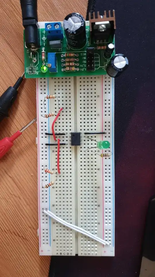
EDIT: I've added some photos to show my circuit and measurements (too big to upload directly).

  1. inv - GND voltage 8.33V

enter image description here

  1. noninv - GND voltage 8.77V

enter image description here

  1. The circuit:

enter image description here

JRE
  • 67,678
  • 8
  • 104
  • 179
Sqoshu
  • 111
  • 3
  • You can find the LM111 spice model at https://www.ti.com/product/LM111/toolssoftware which will give a more accurate representation. – Peter Smith Apr 10 '20 at 11:29
  • Are you sure that by accident you did not "switch" the non-inverting input with inverting one? – G36 Apr 10 '20 at 11:50
  • Also, your input voltage is bellowed the recommended (allowed) input voltage range. The typical input voltage range should be Vcc - 1.2V = 9.14V - 1.2V = 7.94V and above ground 0.5V. – G36 Apr 10 '20 at 11:59
  • I tested your circuit on a breadboard using LM311. I've got 0.83V at non-inverting (pin 2) and 0.39V at the inverting input (pin 3). And the output voltage is at High state (7.5V at pin 7). All this measurements was made with respect to ground ( pin 4) – G36 Apr 10 '20 at 12:04
  • I said this because to get the voltage as I did you need to connect your voltage divider in the opposite way you did. +Vcc 10k---1k---gnd and +Vcc---22k----1k--gnd – G36 Apr 10 '20 at 12:10
  • Yeah I thought so I will mess up the schematic as I said in my main post. The thing is I connected circuit the right way in the real life and it worked as I wrote above. My question is why it doesn't work when I provide lower voltages (in a correct way). Can you explain how you conclude the allowed input voltage? Do you see that in the datasheet? – Sqoshu Apr 10 '20 at 12:14
  • Because now (with 1k resistor at =Vcc side) the voltage at the non-inverting input is \$V_{NI}= 9.14V *\frac{10k}{11k} = 8.3V\$ and at the inverting input is \$V_{II} = 9.41v*\frac{22k}{23k} = 8.7V\$ as you can see the non-inverting (8.3V) is at lower voltage than inverting one (8.7V), therefore the output will be at LOW state.Why? because for a comparator the reference voltage is GND not +Vcc. – G36 Apr 10 '20 at 12:19
  • As for the allowed input voltage range in the datasheet, you will find - "Input common-mode voltage range". – G36 Apr 10 '20 at 12:22
  • I have modified the circuit and added photos in my post to show You what I've got. Now I measured the Vdiff on inv and noninv in relation to ground and I have 8.77V on non-inv and 8.33V inv, so there should be voltage on the output, but as you can see, diode is off (there is a small voltage there, not enough to shine it). Sorry if I still don't understand something obvious.. – Sqoshu Apr 10 '20 at 13:53
  • Is this AVT3072? – G36 Apr 10 '20 at 14:59
  • And if the voltage at non-inv is larger then the voltage at inv input the output will be at a high state (LED OFF). So why you expect otherwise? – G36 Apr 10 '20 at 15:05
  • Yes, it is AVT3072. About the high state, if I uderstand correctly, the comparator should be able to turn on the LED if voltage at pin 2 (non-inv, marked as "+") is higher that at pin 3 (inv, marked as "-"), both relative to GND. Am I correct? – Sqoshu Apr 10 '20 at 15:37
  • @Sqoshu To daczego nie zadasz tego pytania na eletrodzie? No, wrong. If the voltage at non-inverting (marked as "+") input is larger than the voltage at inverting (marked as "-") input the output will be at High state (LED OFF). Read here https://electronics.stackexchange.com/questions/441184/op-amp-virtual-ground-principle-and-other-doubts/441207#441207 – G36 Apr 10 '20 at 15:48
  • Odnośnie elektrody - jakoś nie mam przekonania, ma ona renomę, że jest tam wielu pseudoexpertów. Poza tym z takim pytaniem "prostym" pewnie wyrzucą mnie na kopach. @G36 I get it now, my 470 resistor is connected to high potential so there won't be any differential (almost) when the comparator gives out nearly source voltage.. that's kinda embarrassing.. – Sqoshu Apr 10 '20 at 16:09
  • @Sqoshu LM111 or LM311 is an open collector type (NPN at the output). With means that this type of output can only pulls down the output pin to very nearly GND ("shorts" pin 7 with pin 1). Hence, to get high state at the output you need to add pull-up resistor because open collector output can only provide low state. This is why 470R resistor is mandatory. – G36 Apr 10 '20 at 16:23
  • I really appreciate your input, I will play around with the circuit a little more. Thanks a lot for your answers. I think I have to think about all of this, it's a lot to digest. – Sqoshu Apr 10 '20 at 17:14
  • @Sqoshu Here you can find a very good bedtime reading about Comparator with open-collector output. https://web.archive.org/web/20170721014409/home.cogeco.ca/~rpaisley4/Comparators.html – G36 Apr 10 '20 at 18:26
  • I think I finally understand. When the voltage at non-inverting is higher than at inverting, the output is at "high state", so the voltage output-source is almost zero, so the diode is not shining. When the voltage at n-i is lower than at inv, the output is low, but this means that the voltage differential between output-source is actually high, so the diode shines. The whole problem was me mistaking diode+resistor voltage with C-E voltage, which actually act in the opposite way. Thanks again!! – Sqoshu Apr 10 '20 at 23:06
  • @Sqoshu "output is low, but this means that the voltage differential between output-source is actually high, so the diode shines" I don't like this statement: "differential between output-source is actually high" Can you elaborate a little bit on that? What exactly you have in mind? When the output is at the LOW STATE the output transistor "shorts" pin 7 with pin 4 in our case with GND. So, now we have a path for a current to flow from +Vcc to GND via LED--->Resistor-->internal NPN transistor--->GND – G36 Apr 11 '20 at 08:43
  • I know my terminology wasn't the best, but I meant exactly what you said. The important thing for me, as I said, was to see the difference between the C-E voltage and GND-transistor CE-diode-resistor-source voltages. When C-E voltage is low that means that current is able to flow thru (transistor shorts) and cause LED to shine (so there actually is a notable voltage drop across the LED+resistor). – Sqoshu Apr 11 '20 at 09:55
  • Comments are not for extended discussion; this conversation has been [moved to chat](https://chat.stackexchange.com/rooms/108840/discussion-on-question-by-sqoshu-testing-a-lm111p-comparator). – Voltage Spike Jun 03 '20 at 15:04

0 Answers0