0

I've read a couple of other topics (such as this one and this one) about the lumped circuit abstraction requiring that signal timescales (i.e. the period of the highest frequency signal component) be much longer than the propagation delay of the signals though the circuit, and that the wavelength should be much longer than the largest dimension of the circuit. This makes sense to me as explained in the linked topics above.

However, in the book Foundations of Analog and Digital Circuits by Agarwal and Lang there is this additional comment:

If we are interested in signal speeds that are comparable to the speed of electromagnetic waves, then the lumped matter discipline is violated, and therefore we cannot use the lumped circuit abstraction.

The author of this book also states in this lecture (timestamped) that the assumption is that all signal speeds of interest are much slower than the speed of light.

This is confusing to me since it seems to be saying that the actual wave propagation velocity needs to be small. I don't understand how this is the case since it seems that faster wave propagation would actually help the circuit.

So suppose that you have a circuit with largest dimension \$d\$. You want your signal to propagate at the speed of light, \$c\$. You know that the wavelength \$ \lambda \$ of the signal should be greater than \$d\$, so pick a signal which will have \$ \lambda = 10d \$, as an example.

Then,

$$ \lambda f = v \to f = v/ \lambda \to f = \frac{c}{10d} $$

Then if for example \$d\$ is 1 cm, choose \$f\$ to be approximately 3 GHz. So now the signal period is about 333 picoseconds and the propagation delay is about 33 picoseconds.

Why is this invalid?
knzy
  • 591
  • 2
  • 12
  • _"So now the signal period is about 333 picoseconds"_ - what signal? – Bruce Abbott Apr 08 '20 at 01:32
  • 1
    The speed is always a function of the medium dielectric constant relative to a vacuum which is pretty close to air =1. So the dielectric surrounding the conductor affects the speed. – Tony Stewart EE75 Apr 08 '20 at 01:39
  • I think it could be any arbitrary input signal that travels across the length of the circuit which has a wavelength of 10 cm and travels at the speed of light. Is there something I'm missing? Edit: I posted this before I saw Tony's comment. I get that the speed will be slightly slower than the speed of light due to the material it's passing through but it seems like the author is making a more fundamental claim, right? – knzy Apr 08 '20 at 01:41
  • 2
    "You want your signal to propagate at the speed of light, c" - no, you don't "want" or "not want", signals propagate with speed of light reduced by dielectric constant of material surrounding the conductor. Period. – Ale..chenski Apr 08 '20 at 02:15
  • I wrote it that way to suggest choosing some kind of perfect material that would result in maximum propagation speed. The question is, does the fact that the signal propagates at the speed of light or close to it cause problems even if the wavelength of the signal is much larger than the circuit dimensions? – knzy Apr 08 '20 at 02:25
  • I think you misunderstood him in the lecture...He said that the transition speeds are much smaller than speed of light...what he means is the rise time (or fall time) of signal are much larger than the time it takes for light to propagate the circuit dimension. I think this is inline with what you are expecting. – sarthak Apr 08 '20 at 09:00
  • He’s just talking about the limits of lumped element analysis. As your wavelength approaches the conductor length you need to use distributed analysis, i.e. transmission lines. – user110971 Apr 15 '20 at 09:31

3 Answers3

1

think about it like this, most electrical signals travel at the same speed(depending on the material)

imagine we have a 60Hz sine wave, the wavelength of that is around 6000 kilometers

the wavelength of your signal is 10 cms

The 60Hz signal is not slower, the wavelength is much longer, I think this is the root of your confusion.

for lumped circuits you want to ensure that given a distance all the values of the signal stay the same, they change over time, but not over distance(they do but it is negligible)

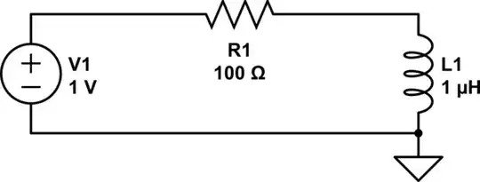
take this schematic, imagine the conductors that connect the resistor to the other components, in your example the wavelength is 10cms right? so in 10cms distance it is a whole period so if the wave starts at 0 goes up to maximum, back to 0 then negative and back to 0 again in the span of 10cm. So what length can you ensure that the values stay the same in the whole circuit? for example the whole circuit is at 0V at a given instant... there are no electrical signals on the way or any point in the circuit waiting to get the memo.

for 60Hz I think most people stop using lumped circuits at a couple of hundred of kilometers, because already at that point there is "travel" delay and reflections and everything else make a significant difference along the conductor.

for a signal like the one you mentioned, even at 1cm the singal changed a 10th of what it would on a full period correct?

schematic

simulate this circuit – Schematic created using CircuitLab

Juan
  • 1,088
  • 7
  • 18
  • Thanks, I think I get what you're saying, that the velocities are the same but the wavelengths are different. The part that still confuses me is when the book's author says the signals are assumed to travel "slower than the speed of light"; how do I interpret this? I know their velocity is lower than that of light in a vacuum because of the material they travel in but I don't think that's what he means. – knzy Apr 08 '20 at 02:06
  • in circuits electricity always travels through certain materials, https://en.wikipedia.org/wiki/Speed_of_electricity – Juan Apr 08 '20 at 02:32
  • Also helpful: https://en.wikipedia.org/wiki/Velocity_factor Note that common materials and transmission lines transmit signals at about half to two thirds the speed of light. Getting close to c is possible if the wires are mostly surrounded by air (or vacuum ideally). – user1850479 Apr 08 '20 at 02:47
0

Statement 1 - If we are interested in signal speeds that are comparable to the speed of electromagnetic waves, then the lumped matter discipline is violated, and therefore we cannot use the lumped circuit abstraction

Statement 2 - All signal speeds of interest should be much slower than the speed of light

Statement 3 - The wavelength λ of the signal should be greater than largest dimension d

Statement 4 - Signal timescales of interest should be much larger than propagation delay of electromagnetic waves across the lumped element

I think all the above statements are actually saying the same idea, but the expression is different.

Imagine that if the signal speed (that is, the change of voltage or current with time) of a node or branch in the lumped circuit model is too fast, then due to the effect of propagation delay, the lumped circuit model will incorrectly predict the corresponding signals on other nodes or branches.

This is simply because the propagation delay is not considered in the lumped circuit model, so the signal speed should not be too fast.

Similarly, if the signal speed is too fast (equivalent to a too high frequency), then the result is that the signal wavelength λ will not be much larger than the largest dimension of the circuit.

Finally, if the signal timescale of interest is too short, it is equivalent to being interested in too fast signal speed, which is also unfavorable for the lumped circuit model.

So in summary, they are all the same argument, but they are expressed differently, which sometimes confuses people.

The One
  • 23
  • 4
0

The velocity of electromagnetic propagation in any medium is:

\$v = \sqrt \frac {1} {\epsilon _0 \epsilon _r \mu _0 \mu _r}\$ where \$\epsilon _0\$ is the permittivity of free space (8.854pF per metre), \$\epsilon _r\$ is the relative permittivity of the material (typically about 4 for most types of FR-4), \$\mu _0\$ is the permeability of free space (\$4 \pi \cdot 10^{-7}\$ Henries per metre} and \$\mu _r\$ is the relative permeability of the material. For copper it is so close to 1 that it may safely be ignored in all but the most demanding of calculations.

As the speed of light is defined as \$c = \sqrt \frac {1} {\epsilon _0 \mu _0}\$ then we can simplify the equation for the velocity of propagation to \$v = \frac {c} {\sqrt \epsilon _r}\$ which yields roughly half the speed of light in most common PCB materials.

The wavelength on the material is \$\lambda = \frac {v} {f} \$

The typical propagation on the surface of FR-4 is about 160 ps per inch and about 170 ps / inch on inner layers.

Now consider a signal with a rise time of 300 ps (about 1.7GHz and not at all unusual in modern devices) which equates to about 2 inches of propagation delay on most PCBs ; what this means is that if there are two nodes on the surface 2 inches apart carrying this signal, then the voltages will be significantly different at those nodes - assuming the 10% / 90% rise time definition the transmitting node will be > 90% of the signal and at the receiving node it will be < 10%.

This means that these two nodes (at any instant in time) will render the lumped model incorrect (the voltages at the two points are very different). This has significant implications on the placement of decoupling capacitors (for instance) on high speed PCBs. For effective decoupling the capacitors need to be less than (preferably) 30 ps distant from the decoupled pin, which is < 0.2 inch (i.e. < 0.1 of a wavelength) - much further away than that and the capacitor may as well not exist.

If the rise time of the signal were 3 ns (where the 90% and 10% points would be about 18 inches apart) then at the two nodes 2 inches apart there will be very little difference (about 11%) between the levels at each point and the lumped model will still be fairly accurate.

The lumped model therefore requires that the distance between any two nodes be < ~0.1 of a signal rise / fall time distance which also equates to 0.1 of a wavelength.

Peter Smith
  • 21,923
  • 1
  • 29
  • 64