11

I'm just starting out in Electrical Engineering and was wondering if anyone could clarify a question about the following RC circuit regarding the LM386.

My question is about the following circuit: http://www.hobby-hour.com/electronics/lm386-bass-boost.gif

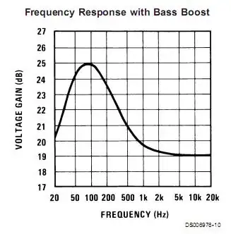
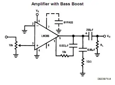
How has adding such a small value cap (between pins 1 and 5) in parallel to the internal resistor of the op-amp boosted the bass?

I have been reading the data sheet; under gain control it says the following:

Additional external components can be placed in parallel with the internal feedback resistors to tailor the gain and frequency response for individual applications. For example, we can compensate poor speaker bass response by frequency shaping the feedback path. This is done with a series RC from pin 1 to 5 (paralleling the internal 15 kΩ resistor). For 6 dB effective bass boost: R . 15 kΩ, the lowest value for good stable operation is R = 10 kΩ if pin 8 is open.

But I do not understand how it works, as far as I knew the bigger the cap the less capacitive resistance it has, so wouldn't a small cap (0.033 µf) as in the diagram be more resistive to bass frequencies? I know I have misunderstood something here.

All help appreciated.

Scott Seidman
  • 29,274
  • 4
  • 44
  • 109
kp122
  • 137
  • 1
  • 1
  • 4
  • The LM386 is an audio amp, but not an op amp. – Scott Seidman Sep 15 '15 at 22:35
  • By the way, one reason to boost the bass is for baffle step compensation in speakers. High frequencies only radiate out the front of a speaker, so they only fill half the room with acoustic power. Low frequencies have a long wavelength relative to the speaker cabinet, so they fill the entire room with acoustic power. So one watt of bass is spread out more than one watt of treble. An increased output of 6dB in the bass (in theory - not quite that much in a smallish room) is required to compensate for the more spread out acoustic power. –  Sep 15 '15 at 22:33
  • The frequency where the baffle step occurs varies by speaker but is often around 500 Hz. –  Sep 15 '15 at 22:33

3 Answers3

10

Think of it this way, at low frequencies, the external series RC network is effectively an open circuit so the amplifier behaves as if the network were not present.

At high frequencies, the RC network is effectively just the 10k resistance.

Looking at the equivalent schematic in the data sheet, note that this 10k resistance is in parallel with the internal 15k feedback resistor.

So, instead of a 15k feedback resistor, there is, at high frequencies, effectively just a 6k resistor , i.e., there is more feedback at high frequencies and thus, reduced gain.

In fact, rather than boosting the gain at low frequencies, the addition of the RC network actually reduces the gain at high frequencies. The effect on frequency response is equivalent; the bass frequencies are amplified more than the high frequencies.

enter image description here

Alfred Centauri
  • 26,502
  • 1
  • 25
  • 63
  • 1
    Thanks, this made the most sense to me. I have now successfully built the circuit, but more importantly I understood why the components went where they went. Just one last thing, when you say "at high frequencies, effectively just a 6k resistor" that's the combined resistance of the 10k and 15k resistors in parallel right? Thanks again. – kp122 Nov 25 '12 at 13:21
  • @kp122, that's correct, the equivalent resistance of the 10k and 15k resistors in parallel is 6k. – Alfred Centauri Nov 25 '12 at 13:53
4

The gain is 2x the ratio of the internal 15K with the 1.35K (& 150 ohm) Without gain modification the amp gives a gain of 20x or 26dB with minimal components.

You can cut the gain by reducing the impedance between 1 & 5 in parallel with the internal 15k.

There is a high pass filter with the speaker and high pass negative feedback that cuts the gain by 7 dB with the 10K and increases to 25dB at 100Hz. At least that is what I get with their suggested values and 100 ohm speaker.

enter image description here

This is what I get with an 8 ohm speaker.

enter image description here

This is what the specsheet shows; Note the differences and note they do not spec the load.

enter image description here enter image description here

Tony Stewart EE75
  • 1
  • 3
  • 54
  • 182
0

The capacitor is in the negative feedback path, not the forward path, so its increased reactance at LF lowers the NFB, which increases the closed-loop LF gain.

user207421
  • 881
  • 1
  • 8
  • 18
  • Thanks for your answer, when you say "negative feedback path" do you mean the negative swing on an AC signal ? If so doesn't the signal only go negative after it has gone through the decoupling cap ? – kp122 Nov 18 '12 at 10:55
  • @kp122 "Negative Feedback Path" is feedback that is in opposite phase to the input. – Anindo Ghosh Nov 18 '12 at 11:14
  • Thanks, so that connection between 1 and 5 is feeding the output back into the input ? – kp122 Nov 18 '12 at 11:35