2

I'm working on a project involving an ATSAMC21. I soldered it onto the board and tested all pins to ensure that; a) they weren't shorted to the adjacent pins, b) they were connected to the nodes that they should be connected to, and c) they weren't connected to any node they shouldn't be connected to. This solder went pretty smoothly, there were only a couple pins that weren't connected, which I touched up.

When I plug it in to my programmer (Atmel-ICE) and try to program it, I get Error 4109 No device detected. I begin checking the power pins, and all are at 5 V, except VDDCORE, which is at 0 V. As I understand it, VDDCORE is a 1.2 V output. I am pretty sure that this is related to whatever is causing the error.

All power pins have bypass capacitors, most are 0.1 uF capacitors, however VDDANA has two 10 uF capcitors separated by a ferrite bead.

I was very, very careful when soldering it, so I don't think I damaged the chip. I have reasonably good equipment, and was using an ESD mat/strap the whole time.

Does anyone know why VDDCORE could be 0 V?

VIN, VDDANA and VDDIO are all 5 V.

Thanks!
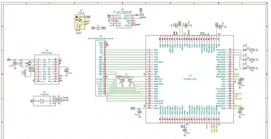
Here's the schematic: enter image description here

According to the datasheet, VDDCORE is a 1.2 V output. enter image description here

AMacDonald
  • 69
  • 5
  • 2
    Would you post the schematics? Are all ground pins connected as well? Is the chip mounted in correct orientation, pin 1 on correct point? – Justme Apr 07 '20 at 20:06
  • 1
    Schematic. I would expect VDDCORE on a CPU to be an input yet you say it's an output ... from what? some regulator? If it really is an input you're not drivin, that would explain the problem. –  Apr 08 '20 at 14:42
  • All the ground the pins are grounded except Pin 24. The pad lifted when I was removing the previous chip, however it is connected to ground internally. The orientation of the chip is definitely correct. – AMacDonald Apr 08 '20 at 21:33
  • VDDCORE powers the core, memory and peripherals (see screenshot from the datasheet). If VDDCORE is 0 V, that would certainly explain why the programmer can't see the device. The question is why it is 0 V. I've checked every single pin with a USB microscop to make sure that it's connected to what it should be connected to, and not connected to anything else. – AMacDonald Apr 08 '20 at 21:37
  • My first thought was that VDDIN was probably not connected, but I measured it yesterday, and again today, and it was 5 V. – AMacDonald Apr 09 '20 at 00:34

0 Answers0