I have a 4-20mA signal and want to feed it to my uC. I found this circuit but dont know how it works.
can any one explain this for me?

or suggest a better solution
I have a 4-20mA signal and want to feed it to my uC. I found this circuit but dont know how it works.
can any one explain this for me?
or suggest a better solution
This circuit is wrong. It's intended to be a differential amplifier using a current sense resistor, but the op amp is drawn with positive feedback instead of negative. Swap the inverting and noninverting inputs if you want it to work.
This doesn't answer what you are asking but may solve the problem.
simulate this circuit – Schematic created using CircuitLab
Figure 1. A current to voltage converter - also known as a resistor - will provide the conversion from 4 - 20 mA to voltage.
VADC = IINR = 165 IIN.
Note that this circuit provides no overload protection.
Response to comment:
With a "proper" conditioning circuit for your 4 - 20 mA signal you could get 4 mA to input 0 V to your ADC and 20 mA to input 3.3 V to your ADC. If you had a 10-bit ADC you have a resolution of 210 = 1024 bits and I bit gives you a resolution of \$ \frac {20 - 4} {1024} = 15.6 \ \mu\text {A/bit} \$.
With the simple resistor circuit 4 mA is input as 0.606 V and the lowest count you will see is 1024 / 5 = 205. This means that your ADC reading will go from 205 to 1023, a range of 819 counts which may be more than enough for your application.
You can scale the result in your μC and remove the offset. So if you wanted 4 to 20 mA to give a percentage you would calculate \$ Out = \frac {In - 205}{819} 100 \$.
Note that one of the advantages of 4 - 20 mA is that you can detect an open-circuit. If the current falls to zero then you know there is a fault or wire-break. (That's called a "live-zero" system.) Without it you don't know. Some systems use 3 mA to indicate, for example, a calibration issue with the sensor. You will lose 20% resolution with this approach but its simplicity may persuade you.
The correct answer to your problem depends on a lot of things, including needed accuracy, the impedance of the previous stage and so on. The following solution is a loose approximation of something that could work:
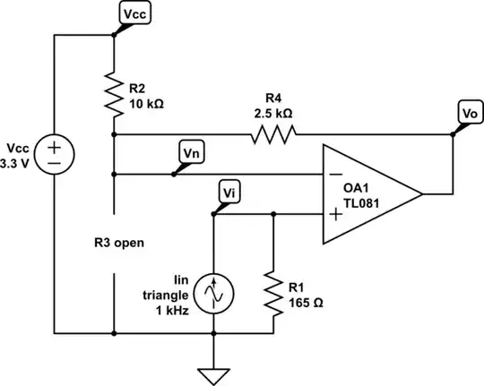
simulate this circuit – Schematic created using CircuitLab
The resistors used are E24 (R2, R4) and E96 (R1), but for their center value the solution is exact. The design steps are basically:
$$\frac {R2} {R4} = \frac {20mA} {4mA} - 1 $$
$$ R1 \left( 1 + R4 \left( \frac 1 {R2} + \frac 1 {R3} \right) \right) = \frac {3.3V} {20mA - 4mA} $$
For an R1=165, R3 evaluates to infinity (open).
You will also want to put a capacitor across R4. Its capacitance depends on the resistances you choose and the desired frequency response of the circuit. It's also important to note that this disregards all of the non-ideal elements of an op-amp, assumes that it has no input offset, that it is rail-to-rail, etc.