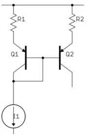
The diode is used to create an accurate bias point which is about 0.7V above the common return voltage. This bias point is relatively immune to changes in the supply voltage. Whether the positive voltage is 9V or 20V, the top of the diode will be at 0.7V. If we replaced the diode with a resistor, the bias point would not have this property. Its voltage will vary with supply voltage. Double the supply voltage from 9V to 18V, and its voltage will double also.
Why does the circuit want to keep the bias at exactly one diode drop above ground? What that will do is put the emitter of Q1 (top of R2) at approximately ground potential, because of the diode drop across the BE junction of the transistor. Thus the emitter is a "virtual ground". It's not clear why that is important without more information about the circuit: where it is used, for what purpose, and any rationale notes from the designer.
That is, why can't the base of Q1 just be grounded, resulting in a bias point that is just 0.7V lower. Maybe there is no reason. Designers do not always do things for rational reasons, but rather for "ritualistic" reasons. It looks as if the designer wanted the voltage drop across R2 to be precisely 20V. Note how R2 is specified as 4.99K, which is ridiculously precise. A 1% tolerance 5K resistor could be anywhere between 4.95K and 5.05K. A 4.99K resistor isn't something you can actually go out and buy, so you cannot actually build this circuit as specified, unless you use a variable resistor and use your digital potentiometer to tune that resistor to 4.99K. The -20V supply has to be just as precise for such a precise value of R2 to make sense. The current through R2 (and hence the collector current of Q1) will vary with the negative supply voltage.

