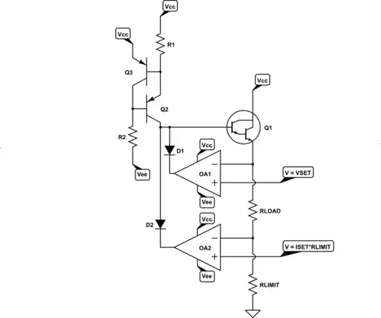
Below picture is a simple voltage regulator(link to simulator):

The current at the op amps output is at nA region(why?), how can I increase the current at the op amps output without adding a third transistor with high gain?
Below picture is a simple voltage regulator(link to simulator):
The current at the op amps output is at nA region(why?), how can I increase the current at the op amps output without adding a third transistor with high gain?
You didn't know what ISRC represented in the schematic I presented to you in the comments. This one, shown below:
simulate this circuit – Schematic created using CircuitLab
The fact that you couldn't work out the meaning tells me a lot about what you haven't yet encountered, or thought about. So this kind of "resets" things back a bit. That's why I commented that you have a lot yet to learn.
As mentioned in the comments, \$I_\text{SRC}\$ is a behavioral current source. When I use the word behavioral I mean that it "behaves like," with the added implications that whatever it is isn't an actual circuit element but instead is a model or idea of some circuitry that behaves like a current source (in this case.)
There are a lot of things that "behave like" a current source. For example, a simple resistor can behave (poorly at times, better in other circumstances) something like a current source. The resistor works better like a current source when one end is tied to a actual voltage source and the other end is tied to something that is mostly like yet another voltage source. Neither end needs to be tied to a perfect (behavioral) voltage source. But it helps a lot when both ends are tied in a way that the voltage across the resistor is, to a rough degree, fixed in magnitude.
In cases where that cannot be guaranteed, more circuitry (usually including active components like transistors or ICs) is needed.
And sometimes you can live with a really crappy current source that isn't very good, but is "good enough."
The main thing is that you should be able to understand from the above circuit that I'm "hand-waving" in the direction of something where the more it looks like an actual current source the more manageable the rest of the circuit is likely to be.
Before moving on, a note of sorts. Because of chemistry rules for batteries, we do have behavioral voltage sources of power that are "pretty good" and are just drop-in components. They aren't perfect. But they are close enough for many intents and purposes. So we are fortunate that the universe has created the kind of physics that allows us to make simple devices that do behave very much like a behavioral voltage power sources. And batteries are commonly found. Off-hand, I don't know of anything that comes out of physics or chemistry, that is a single device, which works like a behavioral current source of power. (But my life is limited in scope.) So, while you may find a single component that provides a reasonable behavioral voltage source, you won't readily find a single component that can be used as a powering current source. But they can be built using a powering voltage source and a passive component (or more.)
Some preliminaries:
Look back at the above circuit. You can see some \$+30\:\text{V}\$ markers in the schematic. These imply something important. A source of power that is a voltage source with a specific value when taken with respect to another point in the circuit often just called "ground." (Though you'll find various English phrases that are similar in meaning.) At the bottom of above circuit, you can see a down-pointing arrow that denotes this "other end" of the powering voltage source.
We aren't specifying where that voltage source comes from and it's not a part of the schematic. It refers to something that is elsewhere and this means you need to provide it as a separate "component" in order to fill in the missing blanks, so to speak. But powering voltage sources are readily available and it's assumed you can "work it out" on your own and add it.
It's also often understood by more experienced readers of schematics where voltage regulation is the point, that the voltage source isn't necessarily exactly \$+30\:\text{V}\$. Especially in the case of fixed voltage-output regulation, there's a strong implication that the \$+30\:\text{V}\$ power source is not regulated and therefore needs regulation. So it really may be a power source whose voltage varies quite a bit. For example, \$\pm2 \:\text{V}\$ around that value. Without additional information, you won't know if the author meant that the minimum was \$+30\:\text{V}\$ or if that might be the average, instead. (It's not usually the maximum -- that would be odd for someone to do to you.) These voltage variations, when they occur, are often low frequency in nature (related to the mains power grid frequency.)
For variable voltage output power supplies, the above comments often still apply. But not always. Sometimes, there is a pre-regulator that really does provide a fairly well-regulated (in voltage value) source of power. So there are some nuances to be aware of when reading a schematic. And as you read the schematic in more detail, you may find indications within the schematic that will better inform you about what you can assume (and not assume) about the indicated power source "rail(s)."
With those out of the way, let's proceed to the idea of high-side and low-side regulation.
Below here are both kinds:
There are times when low-side regulation is used, though more often the low side is about regulating a current-limit instead of providing voltage regulation. But both methods work to regulate the voltage across the load resistance. And if you get enough experience, you'll see both methods are used.
For example, in your circuit exhibited in the question, you illustrated high-side voltage regulation with low-side current-limiting. I just wanted to get these terms drilled into your head so that you aren't flummoxed when you see them used.
A final note at this point. Note that I added \$V_\text{EE}\$ on the schematic. This is there because sometimes the "blob" inside that dashed box (the unknown stuff) needs access to a voltage that is below ground in order to provide sufficient voltage headroom. For example, if you wanted to be able to control/limit the current down to something very, very close to zero (or zero exactly) then there would be no remaining control headroom if the dashed box didn't have a still more negative source to work with in making its observation and providing information to the other part that then operates the controlling output.
Your schematic uses high-side voltage regulation and low-side current-limiting. The behavioral model might be drawn like the blockish diagram on the left. I've also added a very simple change to the diagram, shown to the right, which adds a resistor I'll talk about in a moment.
Note that the dashed block is observing two voltages, managing a control output, and has access to a pair of voltages which should be wider apart than the range you require for the load itself.
On the left side, there's nothing present to turn \$Q_1\$ on so that it can actively supply power to the load. It needs access to base current to settle the recombination debt inside \$Q_1\$. The easiest way to supply that base current is to hook up a resistor as shown on the right. At least this can get the ball rolling. Of course, this is completely uncontrolled operation. It supplies a base current but there's nothing actively adjusting that current. So this is obviously incomplete. But at least we've gone from "not on" to "on."
Before we go further, there's another problem. The control line that touches the base of \$Q_1\$ will have to have a voltage on it that is perhaps somewhere between \$1\:\text{V}\$ and \$3\:\text{V}\$ above the load's voltage (plus a little extra needed for \$R_\text{LIMIT}\$.) Since you are considering (I think) a variable power supply, this means that the voltage across \$R_\text{SRC}\$ can vary a lot. Which means the amount of current it is sourcing is varying, as well. And this places some further difficulties on the rest of the (currently unknown) circuitry. (For example, it might overwhelm the opamp's ability to soak up the extra when regulating a very low voltage for the load.) So we really don't want a resistor there. We'd prefer a current source. Let's add one.
I've added a two-BJT current source to the circuit. One of the BJTs measures the current and the other one is carefully controlled to supply it. For annoying long details on designing one of these (instead using NPNs for a current sink -- the ideas remain, though), see the link here. The nice thing about these is that the current can be regulated well enough that it works fairly well and it's cheap and doesn't take up a lot of space. It's not a perfect current source, though. But for something like this purpose, it's fine. This circuit's current source magnitude will remain fairly stable regardless of your desired output voltage for the load. So it's a "nice to have." And a lot better than a resistor by most measures. Plus, it allows the rest of the circuit to have a current source value that is dependable so the design can proceed knowing what it has to deal with, later.
What should this current source supply? Well, perhaps 3-4 times as much as you imagine that \$Q_1\$ will require. An advantage of \$Q_1\$ being a Darlington is that it requires less current to its base for a given load current than a singleton BJT would require. The disadvantage is that it has a larger voltage drop required. But in this case, with say \$30\:\text{V}\$ available and if you don't need more than say \$24\:\text{V}\$ on the output, then the Darlington is probably fine.
By the way, the 2-BJT current source does, itself, have some voltage headroom requirements -- something on the order of \$1.3\:\text{V}\$ to about \$1.5\:\text{V}\$, or more. So here is yet another one of those "voltage headroom" details. In combination, the current source and also \$Q_1\$, you may require perhaps as much as about \$4.5\:\text{V}\$ headroom, which takes away from your \$30\:\text{V}\$ supply rail. And if the supply rail itself has "ripple" on it and may droop to say, \$28\:\text{V}\$, then this might suggest that you cannot be certain to supply more than \$28\:\text{V}=4.5\:\text{V}=23.5\:\text{V}\$ to the load. And even that has to be further discounted, based upon the voltage drop required by \$R_\text{LIMIT}\$ when operating at the maximum allowable current.
Now, at this point I think we can add in some of what you already had in place.
I haven't plugged in values for the resistors, but the other link helps you work through the details for that part. Just make sure that the current source doesn't provide more current than your opamps can sink -- the opamps should be capable of sinking many times more, in fact, than you are supplying there.
For a Darlington arrangement, and say a maximum current of \$2\:\text{A}\$, you would expect a base current that is perhaps \$1\:\text{mA}\$ or so. So the current source needs to provide more than that -- perhaps 3-4 times as much. And many opamps can sink \$5\:\text{mA}\$ and more. So it should be okay.
There's been no discussion above about dissipation in the various components. Obviously, you'll need to worry about \$Q_1\$. But \$R_\text{LIMIT}\$ may need a bit of attention, just in case.
And now you can see why I wondered, at the outset, about what was supplying base current to your Darlington. Nothing was, in your schematic. And now you can see what I wanted you to think about adding.
The remaining problem, and it's non-trivial, is how you might arrange to supply the two opamps with appropriate voltages that may be independent of your load. For example, suppose you set a specific, regulated voltage with reference to ground into \$V_\text{SET}\$; with a value that accounts for the drop in \$R_\text{LIMIT}\$ for some given load. If the load changes, then the drop across \$R_\text{LIMIT}\$ also changes, while your \$V_\text{SET}\$ remains fixed. This means that the voltage across your load varies a little, depending on the load itself. That's not usually considered a good thing in a power supply that is supposed to be providing a fixed voltage for your load.
Let's look at a cut-and-paste solution to allowing a potentiometer to provide a \$V_\text{SET}\$ that provides a set voltage across the load that remains set, regardless of the load value itself (assuming the current-limit doesn't kick in, of course.)
As you can see, using a potentiometer can be a little more complex than you might otherwise imagine. The added opamp provides a virtual voltage reference for the potentiometer. \$C_1\$ provides a little jitter protection for the potentiometer wiper and \$C_2\$ and \$R_4\$ stabilizes the voltage across the potentiometer. I've added \$R_7\$ as a cheap way to deal with the case where you've removed the load, completely.
And the circuit still doesn't set up a potentiometer for the current limit, which will also need a way to make it remain stable, independent of \$V_\text{CC}\$ ripple. Which means still more parts, though you may avoid another opamp as the ground doesn't need to be buffered.
At first, it seems that all you need to do is toss in a couple of opamps and it's great. But it really turns out that there's a lot more to it, than that. Also, I'm not recommending your approach here. I'm just trying to make it work better, given that you'd want to keep it.