1

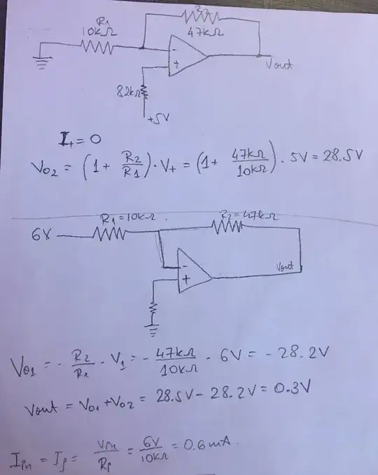
I was trying to answer these questions (picture below) but I am not sure if I did a good job.

the problem

The way that I solved it is shown on this picture below:

the solution

At the inverting part of the op-amp where the two resistors are connected, I supposed it is a virtual ground so the voltage is equal to zero.

Can someone please see if I solved it correctly?

SamGibson
  • 17,231
  • 5
  • 37
  • 58
Kasiopea
  • 73
  • 5
  • The voltage at the inverting input is equal to 5V. It cannot be equal to 6V because the non-inverting input is at +5V. – G36 Apr 03 '20 at 18:43
  • So we have a 1V drop across Ri and the output voltage is 5V - 1/10k *47k = 0.3V – G36 Apr 03 '20 at 18:45
  • @G36 Can you explain me please why there is a 1V drop across Ri ? – Kasiopea Apr 03 '20 at 18:46
  • We know that Vref = +6V and due to the negative feedback action (virtual short) the voltage at inverting input must be equal to the voltage at the non-inverting input. In this case +5V. Therefore the voltage drop across Ri = 6V - 5V = 1V and the current is 0.1mA. so the same current must flow through Rf resistor, and the voltage drop is -4.7V hence the output voltage is 5V - 4.7V = +0.3V https://electronics.stackexchange.com/questions/441184/op-amp-virtual-ground-principle-and-other-doubts/441207#441207 – G36 Apr 03 '20 at 18:51
  • @G36 Thank you for your explanation. If I am understanding this correctly the current that passes through Ri is the same with the current that passes through Rf, therefore there is no current at the inverting input. Right? – Kasiopea Apr 03 '20 at 18:59
  • You are right. For the ideal op-amp, no current is flowing into or flows out of the inputs of the op-amp. – G36 Apr 03 '20 at 19:03

2 Answers2

1

I am rewriting the answer following a point correctly raised by user287001 (merci !). If you want to apply superposition to this circuit, the only sources you can short are the 10-V on the left-side of the potentiometer and the 5-V one. Shorting the \$V_{ref}\$ node actually implies that the equivalent voltage of 6 V is generated with an extremely low resistance, negligible versus the value of \$R_i\$. Practically speaking, in this particular case, the error is small but this is not a rigorous approach hence the needed correction.

The easiest and fastest way is truly to observe that the non-inverting input is biased at 5 V (considering equal inverting and non-inverting pins biases), then the voltage across resistor \$R_i\$ is 6 V-5 V, a 1-V drop which divided by the resistance gives a 100-µA current. The same current circulates in \$R_f\$ considering the zero current going in the (-) pin. Therefore, knowing the bias at the (-) pin and the current in \$R_f\$ leads us to the output voltage:
enter image description here

If we now want to apply superposition to this circuit, there is no other option than determining the wiper position to know the Thévenin resistance at the \$V_{ref}\$ node. How to do this? You consider the potentiometer as two series resistance affected by a coefficient \$k\$ as shown below:
enter image description here

If \$k=1\$, the wiper is 100% in the low-side position and imposes 0 V on the wiper (considering the low-side terminal grounded). If \$k=0\$, the wiper is in the upper position and you read 10 V if the upper terminal is biased to 10 V. With \$k\$ varying between 0 and 1, you adjust the division ratio. By applying superposition around the equivalent circuit shown below, then you can determine where the wiper is positioned:
enter image description here

The, you transform the 6-V \$V_{ref}\$ node by a Thévenin equivalent circuit affected by an output resistance:

enter image description here

We can now alternatively short the 10-V and the 5-V sources to find the exact output voltage which is exactly 300 mV:
enter image description here

And finally, a quick dc-point calculation with SPICE confirms the approach is correct:

enter image description here

SPICE finds \$V_{out}\$ to 300 mV on the output node while the reconstructed version gives 299.999 mV.

Verbal Kint
  • 20,420
  • 1
  • 16
  • 50
  • There's an error. Zeroing Vref to get the gain for +5V is wrong. There's no ideal voltage source which gave Vref. It came from +10V through the pot. The voltage to be zeroed is that 10V. The gain for +5V is less than you claim. Otherwise this is a clear presentation. –  Apr 04 '20 at 10:50
  • @user287001 Why is it wrong? We know that the voltage at Vref is +6V. But even if we include the potentiometer we still end up with the same correct answer +0.3V at the output. So where is the problem? – G36 Apr 04 '20 at 11:31
  • The 6V isn't a voltage source. It's a voltage in a resistor network. A voltage source can be replaced by a wire in superposition calculations. The zeroable voltage source is the +10V one. Simulate and see the difference. The caused gain error is small in percents due the small resistance of the pot but the theory understanding error is 100%. I see quite many here have the same thinking as you but fortunately opinions do not ivalidate math. It stays, no matter how many have opinion it's wong. Only proofs count. –  Apr 04 '20 at 11:37
  • Well, I agree with user287001 that the \$V_{ref}\$ could only be shorted if one considers the output resistance at the \$V_{ref}\$ point negligible versus \$R_i\$ which is not. The SPICE sim actually shorts the 10-V source correctly and applies superposition the correct way. If you want to analytically apply superposition, then you need to determine the wiper position that I also did. For the sake of clarity and in order to avoid confusion, I will rewrite the answer. Thank you for correctly pointing this out. – Verbal Kint Apr 04 '20 at 12:03
  • @user287001 Are you saying that the superposition will give us a different result than +0.3V? And I'm sure that it was not a teacher intend to include the pot in calculations in such a simple problem. – G36 Apr 04 '20 at 12:43
  • Hello G36, I think the simplest way is to calculate \$V_{out}\$ by determining the voltage drop across \$R_f\$. If the teacher intended to use superposition as I originally did, it is not a rigorous approach while the correct one with the wiper position is far too complex (in my opinion) for a simple exam without a solver nearby. – Verbal Kint Apr 04 '20 at 12:50
  • @VerbalKint we do not know the actual purpose of the problem. In addition we do not know if the writer of the problem isn't 100% up to his job. I guess he's competent and he wanted to find those who actually earn the full score. BTW I changed the sign of my vote. –  Apr 04 '20 at 12:58
  • Oui, I agree with your comment and merci for the upvote! – Verbal Kint Apr 04 '20 at 13:08
  • @VerbalKint the formulas you wrote are an image. They look different than those bad text-only formulas I use and the book quality typesettings that many others use. How did you produce those equations? –  Apr 04 '20 at 13:11
  • I copy the electrical diagram in a PowerPoint file and I use MathType to produce nice-looking equations. I then select all and save the picture as .PNG that I include in StackExchange. – Verbal Kint Apr 04 '20 at 13:17
  • @G36 both the common, but theoretically wrong method where Vref is zeroed and the exact method give 0.3V when rounded to 1 digit. If the result is rounded to 3 digits the difference can be seen. –  Apr 04 '20 at 13:27
  • I purposely increased the number of digits to 7 in Mathcad and I have the exact same results of unrounded 300 mV with the complete superposition exercise and the *less rigorous* approach. Do we agree on the potentiometer resistances at least? The unrounded \$k\$ is actually 0.397604848. – Verbal Kint Apr 04 '20 at 13:35
  • I have made yesterday manually the 2nd degree equation work and got the pot division 398 Ohm + 602 Ohm. No disagreement. –  Apr 04 '20 at 13:40
0

There's many hints already given, but you nor others at least haven't published one fact. Here it is:

When +5V is taken into the account with superposition it must be considered to be amplified by a non-inverting amplifier. It's a fatal theory error to consider the feedback voltage divider in that amp to contain only Rf and Ri. There's also the potentiometer.

You must calculate where its slider actually sits when it outputs 6V (=a loaded voltage divider).

Let the resistance parts around the slider of pot R1 be X and 1kOhm-X. You must add to Ri resistance X in parallel with 1kOhm-X and use it in the feedback circuit with Rf. You have skipped this.

There's no voltage source which is in the left end of Ri and ouputs 6V. Placing GND to the left end of Ri when calculating how much the +5V input causes to Vout just assumes that nonexistent voltage source to exist.

The halves of the pot when Vref is 6V are 398 Ohm (upper) and 602 Ohm (lower). One must add 239.6 Ohm to Ri when he calculates how much +5V is amplified. The usual (=wrong) method which simply zeroes Vref gives gain=5.76 for +5V input, the exact method which takes also the pot into the account gives only gain=5.60 for the +5V input.

  • Seems unnecessary to answer the problem questions, since the voltage at Vref is given. – Spehro Pefhany Apr 03 '20 at 20:38
  • I'm sure that the writer of the problem has planned just the same to be thought. The difference in Vout is about 5,8%. –  Apr 03 '20 at 21:11
  • 1
    @user287001 - No it's not. Vref is set at 6 volts in the circuit shown. You appear to believe that the pot is set to a wiper voltage of 6 volts and THEN Ri is connected. That is not what the illustration shows. – WhatRoughBeast Apr 03 '20 at 21:17
  • I calculated the position of the pot by assuming Ri takes current 1V/Ri from the pot. The upper part of the pot is about 398 Ohm and the lower part is 602 Ohm. It's not exactly 4:6 because the current through Ri causes voltage drop. –  Apr 03 '20 at 21:19
  • @WhatRoughBeast It can be instructive to check the accepted answer. –  Apr 05 '20 at 22:54
  • @SpehroPefhany It can be instructive to check the accepted answer. –  Apr 05 '20 at 22:54
  • @user287001 - Fine. Tell me how to do that. – WhatRoughBeast Apr 05 '20 at 23:45
  • Just understand it –  Apr 05 '20 at 23:47
  • By inspection, superposition gives us -4.7*6 + 5.7*5 = +0.3V. Done and out of the exam room enjoying a beer. – Spehro Pefhany Apr 05 '20 at 23:51