1

I want to take two independent differential signals (audio line inputs with unknown properties which may be present or not), remove any common-mode noise from each of them (they could each have different common-mode noise), then sum the desired signals together. I believe I can do this all with 1 op-amp. (Actually I want to output the desired signal differentially, so I will use two of these with inverted output polarity.)

enter image description here

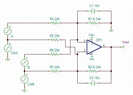
You can assume Rfeedback = Rground and all the input resistors are equal. So then I believe the output is:

$$V_\mathrm{out} = {R_\mathrm{f} \over R_\mathrm{in}} ( A + B )$$

with all the common-mode noise cancelled. Correct?

Are there any problems with this op-amp configuration?

This page calls it a "generic linear operator":

enter image description here

Will the CMRR be reduced by summing on the non-inverting node or anything? I did the math, and CM sources are completely cancelled out at Vout, but I feel vaguely uneasy about it. :)

The input impedance of the inverting inputs varies with the signal, as explained here, but shouldn't matter as long as it's much larger than the source impedance. The common-mode impedance is the important part, and should be the same for all input pairs.

If I weren't trying to do it all in one, I'd use two diff amps followed by a summing amp (followed by an inverter for the differential output). Does that method have any benefits over the single op-amp method?

endolith
  • 28,494
  • 23
  • 117
  • 181

3 Answers3

1

One potential issue I see with this approach is that since the inputs of the op amp will not remain at a fixed voltage, some of the voltage seen on the "sum" inputs of your circuit will be "visible" on the all of the inputs (sum and difference alike). If those inputs are not being driven by low-impedance sources, that could pose a problem.

A better design in some cases, if you have the power-supply margin to accommodate it, may be to have the summing inputs feed into one amplifier wired as an inverter (with a non-inverting input that sits at a fixed voltage), and have the output of that inverter fed as one of the inputs to the amplifier that accepts all the difference inputs. If your sum and difference inputs are intended to be grouped as differential pairs this approach won't be great (the non-inverting inputs will flow through two op amps while the inverting inputs only flow through one) but your original approach won't be either. Your best approach in that case would be to either pass all the sum inputs into one inverting amp, all the difference inputs into another amp, and then take the difference of the two outputs, or else to pass each differential pair through its own instrumentation amp and sum the results. Using a separate instrumentation for each pair would give the by far the best CMRR, but would of course require more amplifiers.

supercat
  • 45,939
  • 2
  • 84
  • 143
1

You have designed 3 differential amplifiers inside one Op Amp, but the CMMR will be reduced from the typical 60 to 100 dB range to 25 dB or so by the mismatch tolerances of all your 1% resistors adding up. If you use a large CM choke over all the wires, this can help significantly. Keep in mind the differential voltage at the OA input must be zero and the output in the linear range.

It all depends on how much CM suppression you need and over what spectrum.

Tony Stewart EE75
  • 1
  • 3
  • 54
  • 182
  • That's a good point I hadn't thought of, but when I simulate it I only get a few dB difference between a single diff amp and a double diff amp. – endolith Nov 16 '12 at 20:11
  • The CMRR could be degraded a lot more than that, if one of the inputs has an unbalanced impedance to ground, but little or no common-mode noise, and another input has more common-mode noise but is balanaced. The imbalance on the first input wouldn't matter since there's little common-mode noise there; the noise on the second input wouldn't matter by itself, since it's balanced. But connect both inputs, and the second input's noise rejection will be totally undermined by the first input's imbalance. – supercat Nov 17 '12 at 00:12
  • Yes I agree and that is mostly capacitive mismatch as audio but sources impedances sohould be matched or referred to zero impedance and then reduce value of input resistor with matching capacitive networks , if you wanted to go this route. – Tony Stewart EE75 Nov 17 '12 at 01:54
0

One easy way to verify this is to compute the gain from each input to the output separately. This is easy because you simply hold all the other inputs at 0. If the negative gain for each channel is exactly the opposite of the positive gain for that channel, then theoretically the common mode component has been eliminated.

By doing this, you can see that the only effect of the additional inputs is that they act as additional voltage dividers reducing the gain of each input. As long as this is properly taken into account with the resistor values, this should work.

I would have done a example illustrating the point, but since you didn't put component designators in your schematic this would be too confusing.

Olin Lathrop
  • 310,974
  • 36
  • 428
  • 915