0

I designed a really simple circuit that's supposed to detect when my car is running.

schematic

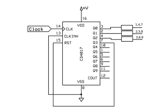
simulate this circuit – Schematic created using CircuitLab

I expect while the engine is off output to be 0V and when running to switch to ~4.5V or something. What I observe is about right when running but when turned off the output does not drop to 0 but rather stays at between 1.8 and 2.0 volts.

Looking at reasons not to use LM741 I'm suspecting any combination of those may be the cause of this.

Given that my above statement is correct and I haven't made any mistakes in my design, what is a good and also cheap op-amp that I can replace the LM741 with?

php_nub_qq
  • 880
  • 8
  • 24
  • 2
    The 741 doesn't have rail to rail outputs. If your negative supply is 0 V, the output will never go below ~2 V, as you found. Solution: choose a different op-amp or provide a negative supply voltage to the 741. This is covered in the 2nd bullet point in the top answer to the question you linked to. – The Photon Apr 02 '20 at 18:50
  • 4
    Even better: use a comparator when you need a comparator, not an op-amp. – The Photon Apr 02 '20 at 18:51
  • @ThePhoton that was my initial idea and through reading (possibly bad sources) I ended up understanding that comparators and opamps are 2 names for the same thing.. – php_nub_qq Apr 02 '20 at 18:52
  • 2
    A 741 or 358 works okay as a comparator, but many newer op-amps won't (they'll be very slow when used in saturated mode), and a modern comparator will be faster than a 741 or 358, and it will be more clearly spec'ed for this application, making it easier to get your design right. – The Photon Apr 02 '20 at 18:54
  • @ThePhoton could you give an example? – php_nub_qq Apr 02 '20 at 18:57
  • There are 1000's. Check the parametric tables at Digikey or Mouser and pick the cheapest one that meets your requirements. – The Photon Apr 02 '20 at 19:00
  • Does this answer your question? [Reasons not to use a 741 op-amp?](https://electronics.stackexchange.com/questions/304521/reasons-not-to-use-a-741-op-amp) – Elliot Alderson Apr 02 '20 at 19:02
  • @ThePhoton I don't know what's the deal with that but it was extremely hard for me to find them. No wonder I failed the first time around. Finally I found LM393 which is cheap and seems like a good fit. Thank you! – php_nub_qq Apr 02 '20 at 19:37
  • 1
    You might want to take a look at [Difference between differential op amp and comparator](https://electronics.stackexchange.com/q/72967/51760) on this site. – Null Apr 02 '20 at 21:05

2 Answers2

3

A LM741 is not suitable for use with 5V supply.

It is not rail-to-rail input or output, you are violating many of its requirements. You need to provide it with both a negative and positive supply to operate as shown.

A single supply device such as LM358 will work better but even then the output will not go to 5V and it also is not rail-to rail input so will not function with the input tie to its own positive supply rail.

As mentioned in the comments, a better solution would be a comparator. the LM393 would be a good fit for this task. It would also need a slightly different circuit with the reference input fed from a voltage within the common mode range (ie not the positive supply rail). As simple divider from the 5V rail would suffice.

Kevin White
  • 32,097
  • 1
  • 47
  • 74
1

The LM393 that you've found should work nicely with some modifications to the circuit.

First, it has an open-collector output -- meaning that it'll pull its output down to 0.2V or so, but you need to use a pull-up resistor to hold the output up.

Second, it only works when its inputs are 2V below its VCC supply. For that circuit, you'd need the negative input to be held at 3V or lower (I'd use a resistive divider down to 2.5V).

You could also go digging some more, for a rail-rail comparator with a push-pull output. It may be that such a device, even if it's more expensive by itself, will save you enough money in extra components and circuit board space to pay the difference.

TimWescott
  • 44,867
  • 1
  • 41
  • 104
  • Thank you so much for the pointers. No doubt you just saved me a lot of head banging. I don't see pulling up and adding some dividers as too much extra work but I'm guessing that's not all that has to be done? As I mentioned, for some reason (probably being a noob) it's really hard for me to find parts that are not super obvious. I'm going to go ahead and try to do it with an LM393 taking into consideration what you have written but in case that doesn't work could you mention an IC that you're referring to as "rail-rail with a push-pull output" – php_nub_qq Apr 02 '20 at 21:59
  • 1
    Also I can just power it with 12V this way I would still be able to use the inputs as they are right now, right? And the output will be at whatever voltage I pull it to so I wouldn't have to worry there. As a push-pull option I found MCP6541 but I'm pretty sure they wouldn't have it in my local store and I'll have to wait for delivery which is quite slow in these circumstances we are in right now.. – php_nub_qq Apr 02 '20 at 22:07