I'm considering designing/building a fairly basic electronic load (constant current, but possibly also constant power and resistance). However, after drawing up a few ideas for the basic operation, I got stuck.
My first idea was to go the digital route, using a MOSFET driven by a DAC as the power dissipator, and a sense resistor + current sense monitor/amplifier read by a microcontroller to adjust the current to the user-set level.
I started doubting it a bit, though, for two reasons:
- I'm not sure if it's "fast" enough. The code would have to check the current in the sense resistor, and presumably use some sort of PID loop or such to drive the MOSFET gate. The monitor I had in mind (TIs INA226 I2C current shunt monitor) can be read at least 1000 times/second, probably 3000; the datasheet is a bit unclear[1]. My guess is that this will do?
- I have no experience with this; would a PID controller be a good fit? More specifically I really have no clue how, better than basic trial and error, to figure out e.g. what the MOSFET Vgs should be to allow a certain current though at a certain voltage (Vds).
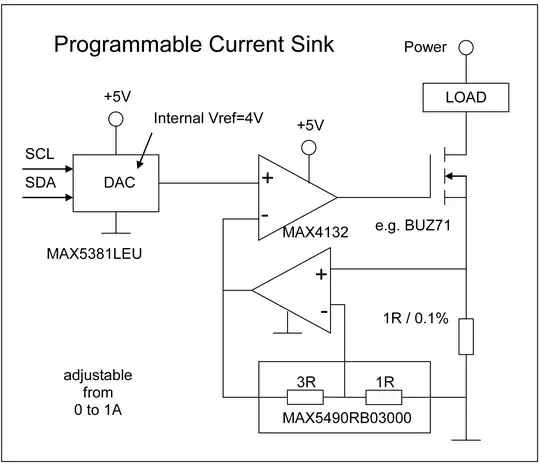
After that, I thought a bit about an analog+digital design: same load and sense resistor, but with an analog instrumentation amp to amplify the sense voltage up, and drive the MOSFET with an opamp with negative feedback. The noninverting input would then be set by the MCU + DAC, but the digital control would only set the current, not actively control it.
The main potential downside I see here is that if the current is low, so that the shunt monitor output should be very low (say 5 mV, for ~ 0.005/5 of the full scale value), the not-truly-rail-to-rail nature of the amplifier might cause issues.
For example, if the "low swing" is 35 mV above ground, it'd essentially "tell" the op amp that the current is 7 times higher than it is, wouldn't it?
This turned out longer than expected. Anyway, the main question is really:
Would the first solution, with digital control by sampling the current at perhaps 1-3 kHz and some sort of PID controller, be a good one?
I figure that if I get that running, I can add more advanced modes such as constant power and constant resistance fairly easily, as opposed to with the analog design.
And if not, is the analog idea any better, and will it work at the case I mentioned with near-ground output?
[1]: They mention as an example that with a 588 µs conversion time and 4 averages, data can be read roughly every 4.7 milliseconds. I'm not sure why that's not every (0.588 * 4) ms instead.