0

Here is a transistor-based simulation of the manually-commutated switched-capacitor SMPS circuit discussed at the bottom of this question, that helps me to think and verify the performance of this circuit. Nonetheless, the linked simulation above does not inspire confidence in me because different transistor combinations result in wildly-ranging efficiencies (from 60% to 87%). That is what this question is about -- What is the correct way to simulate this manually commutated switching mode power supply?

The fall time is critical for the efficiency, and a spark gap (I believe) should have a much shorter fall-time than the best bipolar transistor. That's one aspect of what I think should be better.

Why am I trying to optimize this circuit? I like having deep understanding of things, partly because I am a teacher, and partly because I am an innovator, and both of those benefit from deep knowledge.

EDIT: Above is a better introduction to this question, and below is most of the original content of the question. The question did not ask the question the right way, so it did not get a good response, hence the edit.


Here is the schematic for a teaching transistorless and transformerless Joule Thief that I built, but it had a short-circuiting design flaw -- holding the manual switch closed unnecessarily drained V1: (this schematic is not runnable, but was manually executed)


Figure 1 -- First manual transistorless, transformerless Joule Thief, but short-circuiting

Figure 1 -- First manual transistorless, transformerless Joule Thief, but short-circuiting


Here is the improved design that improves efficiency and prevents the indefinite short-circuiting of the power source, and is a switched-capacitor design. This design has an efficiency of about 80 % so far in simulation (see the link to a bipolar circuit used for simulation).

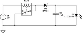
Here is the improved manually-commutated switched-capacitor circuit represented in LTSpice (this schematic is not runnable, but was manually executed):


Figure 2 -- Transistorless and transformerless manual switching capacitor Joule Thief design

Figure 2 -- Transistorless and transformerless manual switching capacitor Joule Thief design


How do I improve simulation of this unconventional Joule Thief?

MicroservicesOnDDD
  • 2,557
  • 1
  • 13
  • 48
  • 1
    [The ultimate simple stupid Joule thief,](https://josepheoff.github.io/posts/voltagebooster) since mechanical switching is allowed. I have driven a [3W 12V LED light bulb with the exact same cuircuit.](https://josepheoff.github.io/posts/leddriver) – JRE Mar 30 '20 at 19:47
  • @JRE -- Thank you for your posts. I loved them. Especially the way of measuring an inductor using the resistor-divider. The additional information that it's a ratio, and the calibration of the scope doesn't matter, it really great, as my Tektronix is from the earliest days. Thanks again. And I basically was trying to use this circuit to teach Joule Thief from the ground up, and as you did, even to those who are convinced differently. ;-) – MicroservicesOnDDD Mar 30 '20 at 20:14
  • 1
    The bit about the ratio and the uncalibrated oscilloscope was kind of important for me, too. [My scope was built in 1965.](https://josepheoff.github.io/posts/oscilloscope-camera) – JRE Mar 30 '20 at 20:34
  • @JRE -- Thanks for that link. I only have an old analog Tektronix, so your link should really help me (by turning my analog scope into a sampling scope). – MicroservicesOnDDD Mar 31 '20 at 00:08

1 Answers1

3

In the vacuum tube days, for car radios they used 'vibrating coils' to make the chopped voltage, which was then fed to a transformer, boosted then rectified to make the B+ (plate) power. This idea could be adapted for making a transistor-less supply I think - maybe a buzzer or suchlike.

That said, a boost topology would probably work better, even with a mechanical switch.


Try this:

schematic

simulate this circuit – Schematic created using CircuitLab

The 'RLY2' is wired as a buzzer; instead you can use an actual buzzer rated for the low input voltage needed. The flyback from the buzzer coil will boost the input voltage.

hacktastical
  • 49,832
  • 2
  • 47
  • 138
  • Thank you! That's great information. I used the inverting-boost topology (even though it is less efficient) for its buck-boost quality of being able to use a voltage source either higher or lower than the destination voltage (about 3). – MicroservicesOnDDD Mar 30 '20 at 19:53
  • That's so cool... How did the coil vibrate? Was it like a speaker coil that used a magnet to produce motion? Or two coils with opposing fields? – MicroservicesOnDDD Mar 30 '20 at 20:35
  • 1
    It worked like a buzzer, with a set of parallel contacts to make the chopped DC. More here: https://en.wikipedia.org/wiki/Vibrator_(electronic) – hacktastical Mar 30 '20 at 20:39
  • I did make one of these, using a speaker (accidentally, actually). When turned on, the cone would move, disconnecting it again. Then, since the speaker was no longer powered, the cone would return to its resting position, bringing the circuit back into operation. Cool! – MicroservicesOnDDD May 02 '22 at 15:45
  • Just curious... I understand if others never gave this a point, but if you thought enough of the question to answer it, then why didn't **you** give it a point? – MicroservicesOnDDD May 02 '22 at 15:50
  • 1
    Different folks have different motivations. I’ve always been more about the answers themselves. Over time I’ve chosen to let go of the whole points business because I feel it’s deeply flawed. – hacktastical May 02 '22 at 17:12
  • I wish they would at least separate it out to two different grades -- #1 will help this site #2 good job with the question. But I agree with you about its flawed-ness, but there's a built in problem, almost a conflict of interest, because those who **could** do something about the point system are bound to be the ones having the **least need* for points (and so don't see the point). :-( – MicroservicesOnDDD May 03 '22 at 15:35