1

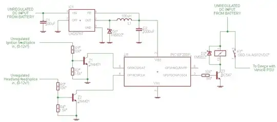
Here is my circuit that's hopefully going to be a custom timer circuit. It has two inputs (ignition wire and headlamp wire), it has one output that will be used to switch a relay.

simple PIC timer with two inputs and one output to relay 
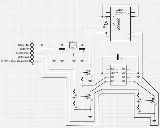
nb. "D31A*" is a Frizting part for a relay that's the closest I could find.

D1 is a suppression diode to protect the transistor from transient voltage when the coil switches. I'm somewhat confident it's wired the correct way, with the diode cathode connecting to the positive side of the coil.

The PIC pin is wired in series to a 10K ohm 1/4 watt resistor to the base of a transistor.

I have chosen BC547 for the transistor, because I have some spares, and the circuit works on my breadboad. I had tried with 2n4401's but the Collector/Emitter continues to conduct after the Base is pulled low, which I found a bit strange and could find no mention of in the datasheet. Perhaps something else is causing it?

The relay I like at the moment is this one: http://www.rapidonline.com/pdf/60-1910.pdf This has spade/blade terminals on the bottom and suits my environment.

Relay Partnum: IMO SRZ-1AT DL 12VDC
Relay Datasheet: http://www.rapidonline.com/pdf/60-1910.pdf

The datasheet indicates the relay is avaialble with a diode built in, but I've been unable to find one and think it may be special-order only.

The load the relay needs to switch is 12V @ 1.5A continuous, 3A peaks. I'm using unregulated vehicle power into the positive side of the coil, is this okay? I had considered solid state relays but they're really expensive! Might one be suitable for this or is a 1.5A continuous with 3A peak too much?

*The device I'm switching on and off with the relay can handle unregulated vehicle power already.

  • What suppression/rectifier diode should I use? How do I know?
  • Is a BC547 okay to go between PIC pin and relay coil -ve side?
  • Is 10k the right resistor value for the transistor? How do I know?
  • Is the relay I'm favouring a good choice for my simple switching example?

Update - New schematic following a telling-off from Olin :)

eagle schematic for simple PIC timer

jon
  • 325
  • 5
  • 11

2 Answers2

3

Comments on your schematic and circuit:

  1. A 7805 is not designed to handle the full range of car power, including short high voltage bursts. This has been mentioned to you before. See previous answers for details.

  2. You have D1 the right way around, but I would make it a Schottky. Those react faster and will be fine for these relatively low voltages.

  3. Fix the schematic to be less of a ratsnest. Traces worming their way all over the place makes it hard to read. See https://electronics.stackexchange.com/a/28255/4512 for details.

  4. Fix the schematic to add part values! You seem to have mentioned some of them in the text, but I'm not going to remember everything you said when looking over the schematic. Do it right, especially since you are asking others to look at it.

Without part values, it is difficult to critique anything but the overall topology. That seems OK, within the detail provided by the schematic.

Added after schematic cleaned up:

That's a lot better. It looks basically OK.

I didn't look up the maximum input voltage of the LM2576. Check that it can handle car power glitches.

The 12 V sense lines driving the PIC inputs look fine.

Check that the BC547 can support the relay coil current with a 10 kΩ base resistor driven to 5V. That should provide about 430 µA base current. If the minimum guaranteed gain of the transistor is 50, for example, then this can support up to 21 mA collector current. That's cutting it close if the relay needs 20 mA, and of course is insufficient if it needs more.

Olin Lathrop
  • 310,974
  • 36
  • 428
  • 915
  • Thanks, Olin. I shall revert in due course. What should I use instead? Still a regulator or the voltage divider and zener diode solution? I think I have missed something in my previous questions so I'll be sure to 're-read' those too. – jon Nov 12 '12 at 19:32
  • 1
    Olin, I am now in love with Eagle. Question updated with revised schematic with the other info you mentioned. 1. I have chosen LM2576T, this can handle up to 40V. I have only copied the example circuit from the 2576's datasheet. 2. D2 on the Eagle schematic is now a Schottky, thanks! 3. Hopefully I've removed some of the ratsnest. It certainly looks clearer to me. 4. Part values added to schematics. Thanks for your help so far! – jon Nov 13 '12 at 17:07
  • That's marvelous, things are starting to fall into place! R5, the 10k resistor driven to 5V gives 500µA to the base (not sure why you have 430µA?). BC547 has 110hFE (minimum gain) so 500µA * 110 = 55mA . The relay's coil current is 16.7mA, so with a 10k resistor the base current is over three times as much as it needs to be. Is this acceptable or should I try and tune the resistor to closer match the relay's coil current? – jon Nov 14 '12 at 09:30
  • ps. in case you were interested, the LM2576 datasheet states "Maximum Supply Voltage 45V". – jon Nov 14 '12 at 09:43
  • 2
    @jon: I got 430 uA because I took the B-E junction drop into account. Figuring 700 mV for that worst case is usually good. As long as the gain you quote is the guaranteed minimum, you're fine. Looks like you need a minimum gain of 40, so 50 or more in the datasheet should be good enough. – Olin Lathrop Nov 14 '12 at 14:22
2

"I had considered solid state relays ... Might one be suitable for this ...?"

Wouldn't it be nice if a "solid state relay" could be used to replace a mechanical relay? Alas, all the "solid-state relays" I've ever used can't be turned off until their output current drops to zero. That's not what we want in an DC battery power application, but fine for switching AC power.

EDIT:

However, I've been told that, in addition to the "AC" SSRs I've used, there also exist:

"DC SSRs" a and "AC/DC SSRs" b c such as the IXYS CPC1918J d and the Panasonic AQZ102 e.

The International Rectifier IPS6011PBF "Self-Protected Intelligent High-side Power Switch" seems specifically designed to do exactly the kind of automotive application you're trying to do. a b


Internally, such "DC SSR" and "AC/DC SSRs" typically use MOSFETs. As Olin Lathrop mentions, there's many other things to consider to get that MOSFET to work properly in all the extremes of an automobile power environment.

In this particular application -- connecting and disconnecting so-called "12 V" automobile power to some device -- you could replace the relay with a P-MOSFET.

Keeping the gate within the gate-source limits specified by the manufacturers is a bit tricky, and requires a few more components.

You still need something -- a few resistors and the BC547 may be adequate -- to level-shift the on/off signal appropriately to drive the gate of the FET.

For under $2 (less than the price of a relay), there are dozens of adequate MOSFETs in standard TO-220 packages at Mouser, Jameco, Newark, Digikey, and other suppliers. For example (randomly selected):

  • Fairchild Semiconductor FQPF15P12: -120 V, 15 A
  • Vishay/Siliconix IRF9640PBF: -200 V, 11 A
  • International Rectifier IRF9640: -200V, 11A

(The seemingly high voltage ratings help it survive the occasional 120 V "load dump" on the so-called "12 V battery power" line).

Something like one of those MOSFETS (plus all the other components mentioned) is in those convenient, easy-to-use SSR packages and almost-as-easy-to-use IPS packages.

davidcary
  • 17,426
  • 11
  • 66
  • 115
  • 1
    While a P FET can be made to work, it is more complicated than you make out and includes some hidden gotchas. The D-S voltage ratings you show should be fine, but keeping within the G-S limit during a spike is going to be tricky. It can be done, but unless you specifically address this issue, your FET will be dead in short order. This is something you have to think about carefully in the circuit design, but you have ignored it completely. – Olin Lathrop Nov 14 '12 at 17:35
  • @OlinLathrop: You are right. So I edited this answer so it no longer completely ignores the issue :-). – davidcary Nov 15 '12 at 18:01