17

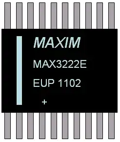
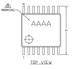
I am trying to identify Pin 1 of MAX3222E, the TSSOP variant (See Page 16 of datasheet), but it doesn't have any corner mark!

Could someone suggest how to identify Pin 1 in this type of situation?

I don't have a high-res camera on me right now, but I do have the chip in front of me, so here's a drawing of everything I see on top (the + sign is just part of the full name MAX3222EEUP+):

enter image description here

boardbite
  • 4,892
  • 11
  • 47
  • 73
  • I just looked at a strip of MAX3222E TSSOP ICs, they appear to have a tiny silver-grey mark at the bottom left. It might be that the lot your IC came from had that mark missing due to a production oversight? – Anindo Ghosh Nov 12 '12 at 20:16
  • 1
    Here's a [nice visual guide](http://www.nteinc.com/faqs/IC_Pin1_Chart.pdf) that covers most of the less usual marking conventions, for DIPs and SIPs anyway. – Fizz Jan 16 '15 at 22:47

4 Answers4

23

If you dig a little deeper on the Maxim website, there's a package drawing for this part.

Pin 1 is clearly indicated.

MAXIM TSSOP

Note 8 says: "MARKING IS FOR PACKAGE ORIENTATION REFERENCE ONLY", which means AAAA is boilerplate text.

Essentially, if you can read AAAA, pin 1 is lower-left.

Adam Lawrence
  • 32,921
  • 3
  • 58
  • 110
  • 2
    +1 for being a very specific and proper answer. Always consult manufacturer's datasheet first before assuming industry conventions no matter how intuitive or obvious they may be. "In the face of ambiguity, refuse the temptation to guess." - Zen of Python – shimofuri Nov 12 '12 at 15:34
  • In this case, it's one of those situations where the part datasheet is ambiguous, but there's a separate package datasheet that tells you what you need. Why separate them? (other than laziness) – Adam Lawrence Nov 12 '12 at 19:25
  • @Madmanguruman I've learnt something new today, thanks. Must look out for multi-part datasheets in the future. – Anindo Ghosh Nov 12 '12 at 20:19
14

The white strip on the left side of the picture looks like a similar indicator to the notch in most ICs, hence pin 1 would be on the bottom-left of the supplied picture.

Shamtam
  • 3,546
  • 19
  • 27
  • I have a feeling that you may be correct; the bottom-left pin may indeed be the one (my basis being ExcitingProjects's answer below); could you clarify what you mean by the "notch" on most ICs? – boardbite Nov 12 '12 at 09:15
  • I've seen a number of Maxim ICs which use both the white strip and the corner mark and so far they've always been on the same side of the IC. – AndrejaKo Nov 12 '12 at 10:12
  • Here's a quick image I snagged from a quick google search, it's a Maxim IC with both a notch and the stripe: http://macpod.net/misc/sx2_tachometer/images/sx2_cn2_tachometer_assembly/u1.jpg Credit to Jeffrey Nelson, since it's his website. – Shamtam Nov 12 '12 at 17:39
14

Chips are marked various ways, but the conventions are pretty universal. In other words, if you find one of these on a unknown chip you can rely on knowing which is pin 1. The conventions are:

  • Pins are always numbered around a chip counter-clockwise when looking at the top. This comes from the old tube days where pins were numbered clockwise looking at the bottom of the tube, as you would when wiring up a socket. Just like with the old tubes, there is something on the package which marks one place a bit more special than the others. This is where you start counting from 1 going around the chip.

  • A dot can be in the pin 1 corner.

  • A notch can be at the pin 1 end. Actually thinking back to the tube convention, the notch is really showing you where the start/stop gap in numbering is when going around the chip. This is totally consistent with tube pin numbering.

  • The pin 1 corner can be shaved off. This is common with packages that have pins coming out all 4 sides.

  • A band or other marking shows the pin 1 gap. This is what you have in the picture above. In your picture, pin 1 is therefore in the lower left corner with numbers proceeding to the right accross the bottom row, then from right to left along the top row. Again, think of going around counter-clockwise when viewed from the top starting at some uniquely marked gap. In your example, pin 10 is the in the lower right corner, pin 11 at upper right, and pin 20 at upper left.

Olin Lathrop
  • 310,974
  • 36
  • 428
  • 915
3

All common TSSOP ICs seem to have pin 1 at lower left when IC is seen from above and text is correct orientation. Then pins count left to right, then on above row they count right to left, like anticlockwise numbering.

This is seemingly also true for all other dual-row ICs as @MartinThompson has pointed out.

ExcitingProjects
  • 672
  • 7
  • 19
  • Didn't know that! I just checked 4 diff chips and this was indeed the case. Generally true only for TSSOP ? – boardbite Nov 12 '12 at 09:13
  • True for every two-rows-of-pins chip I can think of (DIL, SOIC, TSOP, etc) – Martin Thompson Nov 12 '12 at 12:43
  • 2
    From what I've found, pin 1 is usually at the lower left, not the lower right. [Example 1](http://www.analog.com/static/imported-files/packages/PKG_PDF/TSSOP/RU_20.pdf), [Example 2](http://www.ti.com/lit/ml/mtss002e/mtss002e.pdf). – Justin Nov 12 '12 at 12:45
  • 7
    This is just plain wrong. Lots of chips have text on them such that pin 1 is at lower left relative to the text. In fact this is the most common in my experience. You should not rely on text orientation though except when the datasheet explicitly says so. – Olin Lathrop Nov 12 '12 at 14:34
  • Sorry, really bad typo, I meant lower left and then anti-clockwise. That's why I'd written "Then pins count left to right" etc. – ExcitingProjects Nov 12 '12 at 20:00
  • @ExcitingProjects That was not just an error, it was outright counterproductive. Good that you corrected it subsequently. – Anindo Ghosh Nov 12 '12 at 20:18