3

I am trying to tune PID controllers for my drone. There are 3 controllers, one each for Pitch, Yaw and Roll. I have gotten Yaw tuned to a reasonable amount and I am assuming the values for Kp, Ki and Kd are pretty much the same for pitch and roll.

Currently, for pitch and roll, I have Kp = 0.5, and Ki=Kd=0. I am trying to set Kp right now before I move on to Ki and Kd, but no matter what value I put there, the drone (which I have hanging from a string along its center of gravity) oscillates with increasing amplitude until it is completely out of control. Changing Kp only seems to affect how quickly the oscillations increase in amplitude.

Is this the wrong strategy to tune the coefficients or do I have the wrong test setup?

Thank you for your help.

PID Controller code: (Arduino C++)

/**
 * Calculate motor speed for each motor of an X quadcopter depending on received instructions and measures from sensor
 * by applying PID control.
 *
 * (4) (2)     x
 *   \ /     z ↑
 *    X       \|
 *   / \       +----→ y
 * (3) (1)
 *
 * Motors 4 & 1 run clockwise.
 * Motors 2 & 3 run counter-clockwise.
 *
 * Each motor output is considered as a servomotor. As a result, value range is about 1000µs to 2000µs
 */
void pidController() {
  unsigned long t = micros();
  float dt = (t-timer2)/1000000.0;
  float delta_err[3] = {0, 0, 0};          // Error deltas in that order   : Yaw, Pitch, Roll

  // Calculate sum of errors : Integral coefficients
  error_sum[YAW]   += errors[YAW]*dt;
  error_sum[PITCH] += errors[PITCH]*dt;
  error_sum[ROLL]  += errors[ROLL]*dt;

  // Calculate error delta : Derivative coefficients
  delta_err[YAW]   = (errors[YAW]   - previous_error[YAW])/dt;
  delta_err[PITCH] = (errors[PITCH] - previous_error[PITCH])/dt;
  delta_err[ROLL]  = (errors[ROLL]  - previous_error[ROLL])/dt;

  // Save current error as previous_error for next time
  previous_error[YAW]   = errors[YAW];
  previous_error[PITCH] = errors[PITCH];
  previous_error[ROLL]  = errors[ROLL];

  // PID = e.Kp + ∫e.Ki + Δe.Kd
  float yaw_pid   = (errors[YAW]   * YAWp)   + (error_sum[YAW]   * YAWi)   + (delta_err[YAW]   * YAWd);
  float pitch_pid = (errors[PITCH] * PITCHp) + (error_sum[PITCH] * PITCHi) + (delta_err[PITCH] * PITCHd);
  float roll_pid  = (errors[ROLL]  * ROLLp)  + (error_sum[ROLL]  * ROLLi)  + (delta_err[ROLL]  * ROLLd);

  // Calculate pulse duration for each ESC
  pulse_length_esc1 = constrain(holdingthrottle - roll_pid + pitch_pid - yaw_pid, 1000, THROTTLE_LIMIT); //holdingthrottle = 1400, THROTTLE_LIMIT=2000
  pulse_length_esc2 = constrain(holdingthrottle + roll_pid + pitch_pid + yaw_pid, 1000, THROTTLE_LIMIT);
  pulse_length_esc3 = constrain(holdingthrottle - roll_pid - pitch_pid + yaw_pid, 1000, THROTTLE_LIMIT);
  pulse_length_esc4 = constrain(holdingthrottle + roll_pid - pitch_pid - yaw_pid, 1000, THROTTLE_LIMIT);
}
jDAQ
  • 2,517
  • 1
  • 9
  • 19
Plasmabot
  • 39
  • 4
  • 1
    And how much have you changed Kp by? In which direction does speed up or slow down the increase in amplitude? – DKNguyen Mar 17 '20 at 21:49
  • I changed Kp from 0.5 to 1 and it got significantly worse. Anything more than that and it won't stay still at all. – Plasmabot Mar 17 '20 at 22:22
  • 1
    This code is pretty impossible to review without declarations and #defines visible. If you don't think types matter in C, you are very very wrong. Also, are you sure that the Arduino can keep up with PID deadlines? Floating point arithmetic will be extremely slow, given there's no FPU present, just a software lib. – Lundin Mar 18 '20 at 12:46

4 Answers4

6

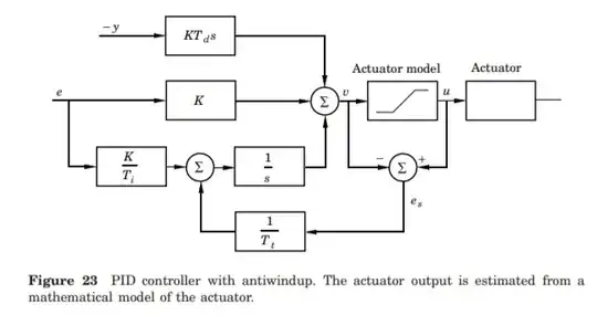
You have some heuristic approach, as copy from textbook or lessons to algorithm. You don't have any wind-up control, hence your integration and differentiation is not affected by changing Kp.

The Ziegler-Nichols type PID is little bit different

$$u=K_p (\varepsilon + \dfrac{1}{T_i}\int\varepsilon\cdot dt \ + T_d\dfrac{d\varepsilon}{dt}) $$

You can see, that this ZN controller changes the ki,kd also when changing Kp. Your issue is probably related to integration and absence of anti-windup mechanism.

One way is to make an incremental algorithm. You do this by differentiating the whole PID formula and then integrating back like indefinite integral with supplementary integration constant.

$$u=K_p\int (\dfrac{d\varepsilon}{dt} + \dfrac{1}{T_i}\varepsilon\ + T_d\dfrac{d^2\varepsilon}{dt^2}) dt+C $$

This transaltes to incremental form when discretized:

U(k)= dU + U(k-1)

$$u(k)=K_p(\dfrac{d\varepsilon}{dt}+ \dfrac{1}{T_i}\varepsilon\ + T_d\dfrac{d^2\varepsilon}{dt^2}) + u(k-1)$$

The limiting and anti-windup is then implemented very simple

if u(k) > max
 u(k) = max
elseif u(k) < min
 u(k) = min

This form can be further improved by replacing integration with trapz rule and differentiation with 1st order lag filter. However with this type of PID you are not able to limit just P,I,D parts separately.

A separate elements of P,I,D is actally an Åström controller. It uses double integrator, the second is so called tracking integrator that subtracts the main integrator when the output is saturated. It's more CPU demanding as it uses square root calculation : \$T_{track}=\sqrt{T_i\cdot\ T_d}\$

EDIT: Controller is described in book: Digital_Self-tuning_Controllers, Bobal et al.

Industrial PID contrller zn3fd source code. The algorithm is incremental : $$u(k)=u(k-1)+\Delta u(k)$$ $$\Delta u(k)= \Delta P+ \Delta I+\Delta D$$

Transfer function: $$ G(s) = K_p(1+\dfrac{1}{sT_i}+ \dfrac{sT_d}{1+sT_d/\alpha}) $$

Note : \$\alpha\$ is a filtering factor of D-component it is reccomended to be from 4 to 20, default value is 10. Bigger value means less filtering, lower value means more filter, it makes no sense to use low values.

http://www.mathworks.com/matlabcentral/fx_files/8381/1/content/help/html/STCSL.htm

// industrial PID controller, author: Bobal et al.
// parameters: Kp, Ti, Td, alpha, u_in, u_max
// inputs: Setponit, ProcesVar 
// output: u

double ek, ek1, ek2, uk1, uk2, Setponit, ProcesVar;
double Ts, alpha, u_min, u_max;
double Kpu, Tu, Kp, Ti, Td, Tf, cf, ci, cd;
double q0, q1, q2, p1, p2;

//initialzation, calcualte coefficients
ek1=ek2=uk1=uk2=u=0.0;
Tf = Td/alpha;
cf = Tf/Ts;
ci = Ts/Ti;
cd = Td/Ts;
p1 = -4*cf/(1+2*cf);
p2 = (2*cf-1)/(1+2*cf);
q0 = Kp * (1 + 2*(cf+cd) + (ci/2)*(1+2*cf))/(1+2*cf);
q1 = Kp * (ci/2-4*(cf+cd))/(1+2*cf);
q2 = Kp * (cf*(2-ci) + 2*cd + ci/2 - 1)/(1+2*cf);

// ISR PID algo
ek2 = ek1;
ek1 = ek;
ek = (Setpoint - ProcesVar);
uk2 = uk1;
uk1 = u;

u = q0*ek + q1*ek1 + q2*ek2 - p1*uk1 - p2*uk2;
//limit
if   u>u_max u = u_max;
else if u<u_min u = u_min;

NOTE: This controller may not be used with disabled integration. You can use float instead of double.

EDIT2:

Computer Control: An Overview It has a java source code for the Åström type controller, this won't suffer if the integration is disabled as the incremental type would. The paper describes the functionality in a very compact form, you have to read it. It has a tracking integrator (reset), filtered D-component (same as Bobal's incremental one) and the output is the sum of P,I,D an excellent example of robust controller.

enter image description here

EDIT 3: If you want to use only the P-control, then you should bias the output with a working point trough a look up table or constant value. With introducing the integral part this is not needed, as the integrator would bias automatically.

schematic

simulate this circuit – Schematic created using CircuitLab

Marko Buršič
  • 23,562
  • 2
  • 20
  • 33
  • "...for pitch and roll, I have Kp = 0.5, and **Ki=Kd=0**. I am trying to set Kp right now before I move on to Ki and Kd, but no matter what value I put there, the drone ... oscillates" it is not an integral wind-up problem, unless the problem is in the interaction between the P controllers for pitch and row and the PID for yaw. – jDAQ Mar 17 '20 at 22:08
  • @jDAQ I don't see a neat P part in your formula. IS this one: errors[YAW] * YAWp? – Marko Buršič Mar 17 '20 at 22:18
  • The op said that he set \$K_i\$ and \$K_d\$ to zero, even though he is implementing a PID, since those terms are zero, he is only using the P part for the pitch and row. – jDAQ Mar 17 '20 at 22:41
  • @jDAQ So sorry, I thought you was the OP. – Marko Buršič Mar 17 '20 at 22:45
  • @MarkoBuršič what do you mean by neat P part? I read that the simplest way to tune PID is to start with only determining Kp and use Ki and Kd to remove oscillations. https://docs.px4.io/v1.9.0/en/config_mc/pid_tuning_guide_multicopter.html – Plasmabot Mar 17 '20 at 23:14
  • Also do you have some example code? I am not familiar with control engineering. My PID function was copied from some other flight controller source code. – Plasmabot Mar 17 '20 at 23:24
  • @Plasmabot I mean, where in your formula is the P-part, I have trouble to understand the code, where is error and where is Kp? – Marko Buršič Mar 17 '20 at 23:25
  • 1
    @Plasmabot I do use codes from scientific articles, books. I don't write my own, because there are scientists that have wrote those codes that are optimised. I can copy paste the incremental PID, but you will have to find also a book on internet, if yo want to fully understand it. – Marko Buršič Mar 17 '20 at 23:30
6

If you're going to use the millwright's method, tune \$k_d\$ first, then \$k_p\$, then \$k_i\$.

And if you're going to use an integrator, put in anti-windup.

TimWescott
  • 44,867
  • 1
  • 41
  • 104
  • 3
    http://www.wescottdesign.com/articles/pid/pidWithoutAPhd.pdf – TimWescott Mar 17 '20 at 22:16
  • Won't the op need a very good filter to stabilize the system (and the right K_d value) that way? I mean, quadcopters are unstable with no controls. – jDAQ Mar 17 '20 at 22:47
  • Are you suggesting using a PD controller only? Or to somehow constrain the values of error_sum within some bounds? Do you have suggestions for what bounds to use? The angles are given by the IMU in degrees and the PID controller loops at approx 150hz. – Plasmabot Mar 17 '20 at 23:21
  • @Plasmabot: I'm not sure how you got your question out of what I said. If you don't know what "anti-windup" means, Google it. You'll find *lots* of information. – TimWescott Mar 17 '20 at 23:26
  • @jDAQ if the OP is starting with the copter suspended from a string at the CG, then (assuming that technique works at all) they can start with \$k_d\$. It may be better to start by Googling "how to tune a quadcopter". In general, if you can get something stable *at all* with very small gains, then you can start advancing one, then the next, then the next -- but you always want to start with the "fastest" gain -- which is \$k_d\$ in this case. – TimWescott Mar 17 '20 at 23:28
4

Double-check your directions and signs. Which direction of roll/pitch/yaw is considered "positive" on your sensors? Which direction does the drone move for a "positive" command of roll/pitch/yaw? And when you calculate error, are you inadvertently doing "measured minus target" instead of "target minus measured"?

If your system is going unstable for even small Kp settings, it seems very likely that you've set up positive feedback. A sign flip somewhere, a misunderstanding about actuators or sensors, or even a sensor mounted upside down, could all give this result.

In passing too, I need to add that your PID algorithm is not following best-practise for the D term, in two ways.

The first issue is that a rapid change to the target will give a big spike on the D term. To prevent this, we usually ignore the target and only differentiate the measured value instead of the error. This turns the D term essentially into "friction", so the faster you move, the more it pushes back - which is exactly what you want for stability.

And the second issue is that differentiation is noisy. To fix this, it's normal to low-pass-filter the differentiated result. The literature tends to use a 1st-order low-pass, but I've found myself that a 2nd-order low-pass tends to give a much less noisy result, although with some extra phase shift of course. If you do go 2nd-order, Bessel filters are your friend here, because you really don't want the overshoot you get from other higher-order filters.

Note that a differentiator followed by a 1st-order low-pass is identical in structure to a 1st-order high-pass, and a differentiator followed by a 2nd-order low-pass is identical in structure to a 2nd-order bandpass. But although the structure is the same, the gains are not. Essentially you're running the filters in what would normally be the "cut" band, and you need to compensate the gain for this. The maths for this is well out of scope of your original question though. If you're interested, we could go to chat on that.

Graham
  • 6,020
  • 13
  • 20
  • If I am finding gains experimentally, can I use a 1st order highpass filter instead of a differentiator + 1st order lowpass filter and not worry about the math? – Plasmabot Mar 18 '20 at 14:56
  • 1
    @Plasmabot You certainly can, yes. But do be warned that if you change the cutoff frequency, you change the gain as well. I strongly suggest monitoring the D term somehow - putting the result out onto a DAC and looking with an oscilloscope is good - and then move the thing around and look at the values. If it looks unacceptably noisy, tweak the filter time constant until you're happy. And then figure out a Kd gain with the filter locked down. – Graham Mar 18 '20 at 16:24
1

Using proportional only, the longer you drive, the more angular momentum you will build up. The system apparently lacks sufficient inherent damping, so proportional-only control will oscillate as it starts applying more and more accumulated torque in each iteration. Derivative (effectively controlled damping) helps control for this, but another likely issue here is that you're probably trying to 'drive' the loop by directly setting your desired output.

Making a control loop stable when you can introduce large driving errors is quite difficult. This is why most industrial controllers actually perform the control in multiple layers and often also have separate control loops for position and torque.

At the level of position control, it's common to use a profile generator where you specify desired accel/decel, as well as desired max velocity, then compute a curve that will move you from your current position to your desired position. Some also take jerk into account (the third derivative), but a simple trapezoidal approximation (accel and decel only with 'infinite' jerk) is a reasonable first approach. This profile generator then generates a smoothly varying change in the target signal passed to your control loop.

The net result of this is that your control loop only ever sees small errors at any given moment. It may oscillate a bit around the target, but it doesn't wind up over long travel distances and overshoot as much, since it's always 'chasing' a nearby target. You'll still get some overshoot and ringing when you reach your target position, but it'll be much more tightly constrained. Your motion will also have a much more controlled feel, with less jerkiness, since you're limiting the accel/decel to account for the inertia in the system.

There are ways to refine this further, such as creating a separate control loop for torque to compensate for non-linearity in the motor response, various additional factors you can add to the control function, like feedforward, and lots of other proprietary smoothing tricks that vendors have added over the years, but the above gives a reasonably solid base to start with.

Dan Bryant
  • 111
  • 4