1

Given the circuit layout here with a 9V input and the 10k ohm thermistor specs given, what at what temp would the green LED light and at what temp would the red LED light?

I am expecting green to come on at about 17.5C and then red to come on at about 37C. Green and red should never be on at the same time and nothing should be on at under about 17.5C.

Is this correct?

Would it work without change for a 3V input? If not, what would need to change?

current design

thermistor values

earlier design (replace blue LED with green

Matt Reidy
  • 13
  • 4
  • 3
    That circuit is quite a mess. It doesn't use the triangular op-amp symbol, the layout is terrible, with unnecessary kinks, branches and crossovers. Many could have been eliminated with the use of the GND symbol. It is very difficult to figure out what's going on. Where did you find it? – Transistor Mar 16 '20 at 21:48
  • Sorry - this is all new to me. I designed it using Autodesk Fusion360... :( – Matt Reidy Mar 16 '20 at 21:50
  • @Transistor - I added an earlier version of the design that might be a bit less confusing. Thx – Matt Reidy Mar 16 '20 at 21:56
  • 1
    Almost a duplicate... https://electronics.stackexchange.com/questions/483979/ntc-thermistor-trigger-led/483984#483984 –  Mar 16 '20 at 22:07

1 Answers1

3

The idea with a schematic is to show the schema of the design. It should read from left to right and, where possible, with the higher voltages at the top. This way signals will generally progress from left to right and current from top to bottom.

schematic

simulate this circuit – Schematic created using CircuitLab

Figure 1. The OP's schematic redrawn.

  • Now it becomes clear that OA1 and OA2 are being used as a comparators. How? Because there is no feedback resistor around either.
  • We can also easily see that the voltage at A will be half-supply because R1 and R3 are equal values. That is our reference for OA1.
  • It's also clear that R2 and R8 form a second potential divider. The voltage at B will be given by \$ V_B = \frac {R8}{R8+R2} \$. Therefore the switching point will be when \$ V_A = V_B \$ which occurs when \$ \frac {R8}{R8+R2} = \frac 1 2\$. You can work that out.

  • You have a second reference point for C so you can work out the switching threshold for that too.

I think you are correct for your 37°C calculation. I didn't work out the other.

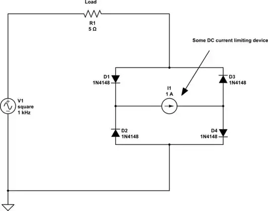
The circuit is a little unusual in that D2 gets its current from OA2 and sinks it into OA1. This has the problem that when OA1 is output high and OA2 is output low that D2 is reverse biased. It's a good idea to keep the LED reverse voltage to less than 5 V or it may be destroyed. Try grounding it in the same way as D1 instead.


schematic

simulate this circuit

Figure 2. Using transistor drivers to work on 3 V supply.

Transistor
  • 168,990
  • 12
  • 186
  • 385
  • Thank you very much - also for the tips on the right way to draw the schematic. I'm just learning and appreciate that feedback. – Matt Reidy Mar 16 '20 at 22:45
  • You're welcome, Matt. You might like to bookmark [rules-and-guidelines-for-drawing-good-schematics](https://electronics.stackexchange.com/questions/28251/rules-and-guidelines-for-drawing-good-schematics) which is an excellent reference - although it covers some advanced topics that you won't need just yet. I spent a lot of my youth hand-drawing schematics and trying to make their meaning clear and neat like the examples in the hobby electronics magazines. Practice if you can. – Transistor Mar 16 '20 at 22:49
  • Don't forget to accept an answer after a day or two if your question had been answered satisfactorily. – Transistor Mar 16 '20 at 23:31
  • trying to get a circuit represents my existing PCB built in CircuitLab so that I can simulate it. The diagram in the OP was my conversion of the physical PCB and I've attempted to replicate it in CircuitLab but I'm not quite sure I have the OpAmps correct etc. For my thermistor (R8) and the sim I'm just assigning values and running the sim. 10K should result in both LEDs off, 6.5K should result in GREEN on and 5.5K should result in RED on. I see very strange voltages at the input sides of the LEDs in the sim... https://www.circuitlab.com/circuit/v9xrr4kj5zx3/templed/ – Matt Reidy Apr 17 '20 at 19:17
  • See ^^^ Thanks for your help! – Matt Reidy Apr 17 '20 at 19:27
  • You've copied the jumbled mess from your original post into CircuitLab. I have exactly the same circuit in a readable form in my answer. Use that and you'll have some hope of understanding it and making sense of the simulation results. CircuitLab allows a DC Sweep and you can sweep the value of R8 between two values that you choose. You can carefully copy my schematic: (1) Hit the edit link under my answer. (2) Edit the schematic. (3) Ctrl-A to select all. (4) Ctrl-C to copy it. (5) Back out without saving. (6) Go you your CircuitLab and paste in my schematic. – Transistor Apr 17 '20 at 20:20
  • I tried your version prior and assigned 6V to the battery and changed the OAs to LM358s but the sim doesn't run... I'll try again - thx – Matt Reidy Apr 17 '20 at 22:00
  • Try mine again. I've added power rails to the second op-amp. Without them the simulator doesn't know what the max and min voltage is so my sim was showing output voltages of 50 MV (yes mega!). Again, edit my question and schematic carefully and run the DC solver while looking at the way I set it up. – Transistor Apr 17 '20 at 22:32
  • There we go - thank you @Transistor! My current problem is that I can't run this off a single 3V cell battery. Using two for 6V works. Is there a way to "boost" the 3V using a capacitor or something? (The DC Sweep is pretty neat!) – Matt Reidy Apr 18 '20 at 00:28
  • Ramping R8.R from 5000 to 11000 with a 6V battery supplies about 4.5 to 5V to the LEDs when needed at about 8.4K and 6K ohms. Lowering the battery to 3V lowers the supply to the LEDs to about 2.5V which either isn't enough to drive them or maybe not enough for the LM358... – Matt Reidy Apr 18 '20 at 00:42
  • I didn't know that by "3 V input" you meant a 3 V *supply*. Rail to rail op-amps have poor output current capability when close to the rails. See Figure 2 for transistor solution but note that I didn't invert the inputs of the comparators and I may have failed to comply with "nothing should be on at under about 17.5C". – Transistor Apr 18 '20 at 09:15