0

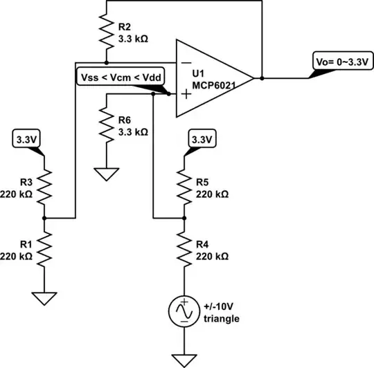
I need to convert +/- 10 V sine to 0...3.3 V sine. I made a circuit from this topic How to change -10;10V sine wave to 0;3.3V dor ADC

The one with two MCP6021's.

The problem is that at some point some irregularities happen Circuit

In this spot when I checked with oscilloscope it looked like it's cutting off bottom half of the sine instead of raising it with 1.65 V.

Could anyone explain the issue to me please?

In simulations it works fine, but in reality it doesn't.

  • Uminus seems to be connected to ground? In the circuit provided Uin is V1 sine between ground (0) and amplitude of V1 voltage. Can you share circuit diagram from simulation tool, as well as its simulation results? Can you share circuit diagram of your real device? – Anonymous Mar 03 '20 at 17:36
  • 1
    In your real circuit, OA2's output is being held at +1.65V? – Bort Mar 03 '20 at 17:38

1 Answers1

1

There is a hidden error of negative common-mode voltage on Vin due to the bipolar input.

A simple solution is to pull both Vin+/Vin- up with 220k To 3.3V or the equivalent circuit to make Vcm increase within the Rail to Rail limits with some margin. (0.4V)

schematic

simulate this circuit – Schematic created using CircuitLab

Tony Stewart EE75
  • 1
  • 3
  • 54
  • 182