The lowest-cost solution would consist of the following:
- a mains AC phase detector (a zero-cross-detector)
- an opto-triac (without a zero-crossing circuit!) such as the MOC302x
- a triac or a pair of SCRs to be driven by the optocoupler
- Safety, safety, safety, since you're working with relatively dangerous voltage levels!
How does it work? A triac will conduct if you excite it with a pulse. It will keep conducting as long as there is some current flowing through it.
Let's say you fire the triac at a random time. Every 8.33ms, the AC voltage is equal to zero. When that happens, the triac will turn itself off. So, if you fire the triac right after that zero-crossing time, it will conduct almost continuously. If you wait 4.166ms after the zero-crossing, the triac will conduct for half of the AC sine wave period. As illustrated by the following image:
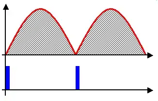
If you know the moment when the AC sinewave reaches ~0V, you can delay the triggering pulse. The longer you wait, the smaller will be the 'chunk of energy' supplied to your load. There are many zero-cross detector circuits around. Use google to find the one you can understand the best. I highly recommend using a design that utilizes an isolation transformer, just to keep it safe. You could probably use a low voltage AC adapter for the purpose of monitoring AC.
Okay, so how do we fire a triac? The easiest and cheapest way is by using an optocoupler with an output designed to work with triacs or SCRs. Your arduino will essentially light a small diode that will trigger a light-sensitive semiconductor isolated from the rest of your circuit.
If you don't know anything about triacs, first read about thyristors/SCRs. A triac is basically a slightly different thyristor.
Wish you luck with your project.