8

Would someone have experience with driving a pair of LM3886 Overture Power Amplifiers in BTL with up to 100 KHz sine wave?

My parameters:

  • Frequency band of interest: 20KHz to 100 KHz, sine wave
  • Load is pure capacitive, 10-20 Ohm, 5000 pF
  • Power delivery to load: Up to 50 watts RMS
  • Amplifier Configuration: Bridge Tied Load
  • THD / noise, even up to 5%, not a concern
  • Power: Unregulated +/-35 Volts 5+5 Amperes, 10000 uF reservoir capacitor on each rail

Found a useful whitepaper on BTL with LM3886. However, the operating band for this paper is 20Hz-20KHz.

Starting with the schematic from here: enter image description here

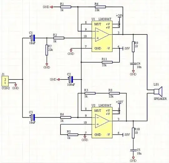
Of course, input / output / feedback part values shown would need to change for my frequency band of interest, but my analog-fu is a bit rusty circa 1988, so some brushing up to be done.


My questions:

  • Will this work at all? (I don't see why not, but found no useful information found)
  • Any suggestion on a different single-chip power amp to use instead?
  • What is the gain I should design for?
    • More immediate interest: What input Vpp range is needed?
  • What do I need to take care of in terms of feedback / compensation and stability management
    • Info found so far is for audio frequency range, little mention of high frequencies
    • Found a discussion about oscillation at high frequencies (50KHz+) due to electrolytic caps.
    • No info found about driving capacitive load, as audio = inductive loads, typically.
    • How do I get an essentially flat response for 20-100 KHz?
  • For the power supply:
    • Recommendations between single and dual bridge
    • Is the 5 + 5 ampere calculation good, with reasonable headroom?
    • Is there a switching power supply alternative that might save cost / reduce heat?
  • Anything else critical to address even at experimental stage (One-off DIY, isn't going to production)

Any other inputs / help / advice gratefully accepted!

Anindo Ghosh
  • 50,188
  • 8
  • 103
  • 200
  • I am making a similar design and need help with same questions like this. – ExcitingProjects Nov 16 '12 at 07:00
  • Are you trying to drive your sonar thing Anindo? I've got a decent power amp and controller circuit I use for driving 600kHz at about 100Vp-p into a 90% reactive load. I'm sure it will breeze 100kHz. Off-hand can't remember the FETs (monday again!) but it uses a Variable dc-to-dc to feed a power amp. – Andy aka Jun 27 '13 at 17:34
  • @Andyaka I'm driving a Langevin Ultrasonic Transducer, pure capacitive, 10-20 Ohm impedance (at resonant frequency), 5000 pF load. Power levels now relevant are of the order of 500 Watts at resonance, the 50 Watt transducers were for a prototype where I finally used a pair of high-current op amps (3 Amp). I still need a good solution for the 500 Watt version. – Anindo Ghosh Jun 27 '13 at 17:38
  • Darn it 500W is a tad too much methinks for my circuit. At resonance does it turn resistive i.e. is it real or VA power? – Andy aka Jun 27 '13 at 17:40
  • @Andyaka The 500W is VA power. Real power is around 1.5% to 10% depending on the quality of the bolt-clamped transducer. The cheap 10% ones are similar to industrial ultrasonic cleaner transducers, they get quite hot at max power. Also, is your circuit amplifying arbitrary waveforms, or is it a square wave (you mentioned FETs)? The challenge is with the sine waves (which are coming from an Analog DDS IC). For square waves, the generic commercially available H-Bridge type ultrasonic generators work perfectly, even in the 3 kW range. – Anindo Ghosh Jun 27 '13 at 17:47
  • It starts as square to get thru the power stage then gets filtered (at the power level) to be reasonably sine - it's used for coupling power to electronics mounted on a shaft such as an aero engine - it's a bit like a Tesla coil setup with the coupling being aweful it has to be tuned. Litz wire and a few hundred volts peak to peak on the last one but at 600k and that's really hard. Like i say, 100k should be easier on the FETs but it will need some custom magnetics I'm sure!! If you can live with a fixed frequency installation it might be worth considering. – Andy aka Jun 27 '13 at 18:05
  • @Andyaka No, fixed frequency is not an option for this particular application - the frequency drifts with temperature and some other factors, plus between transducers there is a fair bit of difference. Frequency needs to be periodically re-tuned for maximum power output (i.e. resonance). There's a current measurement resistor of 0.1 Ohms in series with the load, for this purpose. – Anindo Ghosh Jun 27 '13 at 18:40

1 Answers1

1

Your load looks mostly resistive, not capacitive. I think most design include a large capacitor between the speaker and the driver to block DC since you're only interested in audio. Then it'd be a capacitive load (maybe that's the intent?). Anyway make sure you don't use a polarized capacitor.

Your AC coupled input is too heavily filtered. You need to reduce that 22kohm.

You don't need that large filter on the mute pin either unless you're actually using it.

You might want to add a capacitor in parallel with your feedback resistor to provide the high frequency filtering.

Did you read the datasheet? It's got some good design tips.

Analog Arsonist
  • 957
  • 5
  • 10
  • "*Load is pure capacitive*". Did you read the question at all? – Anindo Ghosh Jun 16 '13 at 04:01
  • "pure capacitive" followed by 10-20ohms. That's a pretty heavy resistive load but it looks like maybe that 10-20ohms is at a specific frequency. Look at page 22 "reactive loading". They talk about decoupling the load with a real resistor. There is a spice model so you can perform an open-loop analysis and check your phase/gain margins for any capacitive load. There are also compensation techniques (cap from output to input of opamp) to improve stability. – Analog Arsonist Jun 29 '13 at 14:59
  • Yes, 10-20 Ohms, or less for the higher wattage transducers, is at resonance. At +/- 100 Hz, this rises past 600 Ohms, all the way to 10k+ far from resonance. Langevin type piezo transducers have a terribly sharp resonance and very high Q. Also resonant frequency changes between units and over time due to environmental conditions. Real part of impedance is minuscule, just the leads and solder mostly. – Anindo Ghosh Jun 29 '13 at 21:06
  • Also, this application is not at all audio, the resonant frequencies of the transducers are a minimum of 20kHz, up to 100kHz, purely ultrasonic. This was stated in the original question. – Anindo Ghosh Jun 29 '13 at 21:11