1

I'm trying to turn on a power LED using LM555 timer as input signal of IRF630N N-channel power MOSFET as Fig1.
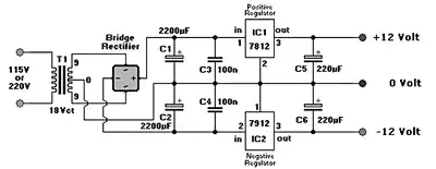
Fig1. pulse generator and switching circuit. Fig1. pulse generator and switching circuit.

  1. Here is the output of LM555 Timer (Not connected to MOSFET). How can I remove the beginning upper voltage as Fig2 (voltage in red circle)? I need exactly a clean square pulse.

Fig2. LM555 Timer output. Fig2. LM555 Timer output.

  1. When output of 555 timer is connected to gate voltage is completly changed as shown in Fig.3. Why this is happening?

Fig3. output of timer connected to gate.

Fig3. output of timer connected to gate.

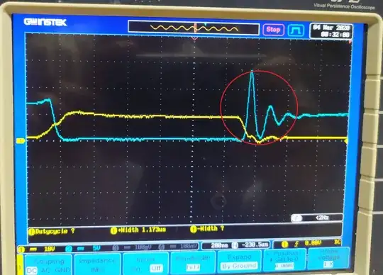
  1. t on is 1us, and t off is 9us. Drain voltage (blue diagram) is supposed to be like Fig.4. How can I remove ringing shape of drain voltage?

Fig.4. Voltage spikes Fig.4. Voltage spikes

  1. When a big time division is used (more than 200 ms) Drain output is like Fig.5. When I zoomed in the image timer555 out pulse wasn't square, and also it seems Mosfet does not switch good. What should I do?
Fig.5. Output for 500ms time division. Fig.5. Output for 500ms time division.

Is there other ways for pulse generating (t on 500ns - 1us and t off > 1us)? Any help is appriciated.

update1: Power LED link.

update2: Final application Images added.

Mehran
  • 235
  • 1
  • 5
  • 15
  • 1
    Looks like a layout problem. (parasitic inductance resonating with device and parasitic capacitance.) Why the resistance in the source? You want a solid switching action which the resistance between source and ground will prevent. Maybe add a little resistance in series with the gate to slow the edge a bit. – John D Feb 22 '20 at 21:51
  • when driving Power LED an one ohm resistance is placed to compute the current. – Mehran Feb 22 '20 at 22:52
  • 1
    If you mean one ohm in the source, it is probably OK. It's a lot different from the 22K you show in the schematic, you should clarify your schematic if that's the case. – John D Feb 22 '20 at 22:55
  • @JohnD, Oscilloscope images are related to schematic, I used different resistors to check if MOSFET is working good. I forgot to take pictures of real circuit responses, I'll add it later – Mehran Feb 22 '20 at 23:11
  • Which MOSFET are you using? – Bruce Abbott Feb 23 '20 at 00:27
  • please update the resistor values in the schematics ..22K and 33K.. are they really the same? – User323693 Feb 24 '20 at 07:55
  • @BruceAbbott, The topic is updated with more information. IRF630 and 640 are used. results are for irf630. – Mehran Mar 04 '20 at 00:47

3 Answers3

1

1. Improve your MOSFET layout (edited)

First remove any resistance or use a small current shunt (less than 0,1 Ohm) between the source of the MOSFET and the ground. A N-MOSFET is controlled by the voltage between gate and source Vgs. The LM555 output is referenced to the ground, so must be the source of your MOSFET.

2. Take care of the LM555

Then add a small resistor between the LM555 output and the gate. The LM555 seems to be able to source only 200mA (according to datasheet http://www.ti.com/lit/ds/symlink/lm555.pdf), so according to the voltage you use and inner gate resistor of your N-MOSFET, check that you are not trying to drive to much current from the LM555. This can be the explanation of the voltage drop when connecting the MOSFET.

3. Control the LED current (edited)

Finally, if you are trying to drive a power LED, you should consider to drive it with a current source. Power LED must be current-controlled as forward voltage is dependent of LED temperature and current flowing through the LED. Take a look of page 2 and 7 of your datasheet. Variation are about 10% for both. So if you apply a constant voltage to the LED you will get a various luminosity as the LED gets warm.

JRE
  • 67,678
  • 8
  • 104
  • 179
Mathieu G.
  • 188
  • 1
  • 9
  • 1. an 1 ohm resistance is placed in source to compute the current. What do you mean about "The LM555 output is referenced ..."? I don't get it, please explain a bit more. 2. I'll do it tomorrow. 3. LED link is added as update1. – Mehran Feb 22 '20 at 23:12
  • 1
    As already said 1 Ohm may not be so critical. However your led will drive about 1A, it means 1V will appear on your current resistor. It also means 1W will be lost in heat, that's not efficient. Consider a smaller resistor and use an amplifier to measure current. The LM555 output is a voltage with ground as reference. To command the MOSFET, gate voltage must be reference to source. So source and ground must be very close. – Mathieu G. Feb 24 '20 at 07:11
1

1 and 2 This is happening because everytime you connect something to something else there is a reaction. Each device, each pin has its own resistance, capacitance and inductance. Nothing is perfectly inert. Start with a reistor to the gate (1k is a good number, less if you want to increase speed but it must be at minimum 140 ohms. You can go as high as 60K.) To erase the small spike, you can add a small capacitor (between 100 and 1000pF) and perhaps a small resistor (between 100 ohm and 1K) before the capacitor. But it raises the question: Why do you want to remove this spike so bad? It has no effect whatsoever on the switching of the LED. So, IMO you let it like that, unless you have a very good reason. The resistor to ground should be bigger: Between 22K and 1M. 100K is usually a good value. 10K is a bit too low. You waste current for nothing.

3, It's also normal for the same reasons. I guess the resistor between the LED and the current source is too small. I talked about 1 ohm. That's not a resistance. It doesn't regulate anything. You need at least 10 or 20 ohms, just to be safe. And the voltage from the power supply applied to the LED (before the resistor) must be as close as possible to what the LED needs for a certain amount of current and light output. (A little bit less than indicated in the datasheet). The best way to do that is to use a constant curent supply but for a single led or serie of led and lower than max power, a constant voltage source is acceptable but you must have at least 10 ohm resistor before or after the LED (it doesn't matter). But if you do that with, say 2V difference you will waste too must current through the resistor + it will heats. If you still see and worry about a spike after the LED, connect a 1000 pF between the LED cathode and ground.

  1. Add a 1uF capacitor near the Vcc pin of the 555 clock, if there isn't any yet. Ass another 10 uF somewhere on the Vcc line. The LED should have penty of reserve (100uF to 1000uF) too. But this is supposed to be present in the power supply. It doesn't hurt to add some reserve thought.

  2. Check that a good 5V is applied to the gate of the mosfet. The higher the voltage, the best (just don't come too close to the max, usualy 20V). At 5V the mosfet is conducting optimaly. At less than 5V, you will see some unwanted resistance and it;s not good. At 2,8V it can even be dangerous,

Fredled
  • 1,820
  • 9
  • 17
  • Thanks for your response, 1. Flashing is used for fast imaging, input spikes has unwanted artifacts on captured images. As shown in Fig.3, Drain voltage changes as input voltage spikes. I need same luminance (clean and steady voltage) for all 1us which LED is on, so I need to remove this effect. – Mehran Apr 03 '20 at 14:37
  • @Mehran I understand. And it's a big LED. It will be difficult to put a resistor in serie (with a capacitor in parallel) to create a "RC snubber" (see other answer). It should be 10 or 20 ohm, no more, maybe 5W or 10W wirewound resistor. You must calculate the power dissipation of the resistor. If it's just a short flash once every 5 min, then you can cheat a little bit. I recomend a capacitor of 100V if the voltage is 35V. or at least 50V. How many µF? There are calculations but in this case the best is to test several values. Maybe 0.1µF. – Fredled Apr 03 '20 at 16:37
  • Actually I haven't tested the recommendations, I'll do it as soon as I can. – Mehran Apr 04 '20 at 00:16
0

I used a RC snubber circuit as described here to remove voltage spikes.

Mehran
  • 235
  • 1
  • 5
  • 15