This is more of an intuitive answer rather than a very technical one.
Let's look at the following circuit. In layman's terms, here a power source of 5V(connected at the top) is trying to establish a current in the circuit. But a battery connected with opposite polarity(with respect to the source voltage) is trying to oppose that current.
Now consider this next circuit. Here the battery connected is of reduced magnitude. Hence the current in the circuit increases.
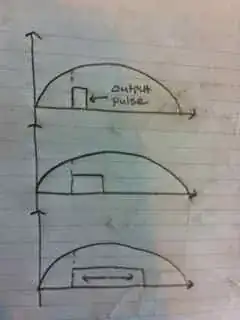
As you further reduce the battery voltage, the current in the circuit further increases.
The current goes on increasing and reaches the maximum value when the battery voltage becomes 0V.
Now consider this simple NPN Bipolar Junction transistor circuit.
Here voltage from Collector to Emitter is playing the role of the battery which is opposing the current (presently let's not consider what factors are really responsible for controlling this battery Voltage). The maximum current could flow in the previous circuit, when the battery voltage was at a minimum value (0V in that case). Similarly here too, the maximum current will flow through the circuit when this Collector to Emitter voltage (represented by battery) is minimum.
Now, In transistors this Collector to Emitter voltage cannot go to zero but to a certain minimum value. This minimum possible voltage value is generally given in datasheet for a transistor by the name of 'Collector-Emitter Saturation Voltage'. It is typically around 0.2V. The current which would be flowing in the circuit at this minimum Collector-Emitter Voltage is called Saturation Current. It is maximum possible current which can flow in the given circuit and hence the name Saturation Current.
So saturation current depends not only on the power input to the circuit (5V in this case) but also on the magnitude and position of the circuit elements (like Resistor) connected in the circuit. You can always apply some KCL equations and find out the saturation current for your circuit.
But how this 'Collector-Emitter Voltage' changes by changing certain circuit parameters? How can we make this 'Collector-Emitter Voltage' go down to the minimum 'Collector-Emitter Saturation Voltage'? These are the questions which would require further analysis and calculations.