I'm trying to figure out how to read-in a configuration to the small ATtiny10 microcontroller. I want to find out 5 or 6 different configurations, adjustable by hardware into one IO using the same firmware to make settings in the program. At the moment there are 3 DIP-switches used for this, and as you expect we need full 3 IOs. This corresponds to 8 different configurations. Can this be reduced to only using one IO? So I can switch over to an ATtiny10...
Of course I could also use the internal ADC and attach a voltage divider. Maybe it could also be purely digital. Internal Pull-Up (software switchable) has according to data sheet 20 kΩ to 50 kΩ. I come up with different possibilities to use an IO as configuration input:
- (a) Pull-Up (high impedance) e.g. 470kΩ to VCC/VDD,
- (b) Pull-Down (high impedance) e.g. 470kΩ to GND/VSS,
- (c) Pull-Down (low impedance) e.g. 1kΩ to GND/VSS, if the internal pull-up resistor is on, it will be overridden during a read-in with internal pull-up set,
- (d) Using an RC-element, see schematics,
- (e) RC-element using another configuration.
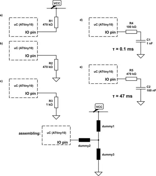
simulate this circuit – Schematic created using CircuitLab
My idea and procedure (for instance):
- Set IO to input, internal pull-up on, wait a minimum of 500 ms,
- Read input: High on a), b), d), e) ; LOW on c) -> case (c) detected;
- Internal pull-up off, no wait;
- Read input: High on a) d) e) ; LOW on b) c) -> case (b) detected;
- Wait 1 ms,
- Read input: High on a) e) ; LOW on b) c) d) -> case (d) detected;
- Wait 500 ms,
- Read input: High on a) ; LOW on b) c) d) e) -> case (e) detected; and case (a) also detected.
- If d) or e) was detected set output pin to GND, else keep it as input.
In these cases, I therefore only need to mount two components on the circuit board in three designated places: (a) 0R + 470k (b) 0R + 470k (c) 0R + 1k (d) 100k + 1n (e) 470k + 100n; with all the same component size (e.g. 0603)
I hope that you can support me with further ideas?