0

CONTEXT

My son recently noticed that the lights dimmed when the refrigerator turns on. This question has been posed elsewhere [1]. The responses in [1] do not meet my needs.

In my humble opinion, to satisfactorily answer explain how come the lights dim, I must first know what is the simplest schematic diagram of a compressor. It appears that there is a circuit diagram in [2]...

QUESTION

In your opinion, what is a minimum-working example for the schematic diagram of a compressor? Please explain why you think your minimum-working example is the sensible choice.

BIBLIOGRAPHY

[1] https://diy.stackexchange.com/questions/98459/why-is-my-fridge-causing-my-lights-to-dim

[2] Refrigeration compressor circuit, help trying to reverse engineer it

Huisman
  • 10,594
  • 2
  • 19
  • 40
Michael Levy
  • 147
  • 6
  • 1
    For the purpose of answering this question, you can probably just pretend it's a big light bulb. – user253751 Feb 05 '20 at 13:27
  • What does a big light bulb mean to you? To me its a non-Ohmic circuit component. Are you suggesting it has a relatively high resistance or a relatively low resistance. With a one-component schematic, can you explain how come the light first dims, and then gets brighter again? – Michael Levy Feb 05 '20 at 13:38
  • 1
    A lightbulb also draws a big current when it's cold, then a smaller current when it's hot. – user253751 Feb 05 '20 at 13:48
  • 1
    Loose components in electrical cabinets can create a lot of heat. The problem with the dimming may have been that the heating caused the components to expand, along with arcing. – Ron Beyer Feb 05 '20 at 13:49
  • Start current will be 5x run current which should not cause much dimming of lights unless the resistance in the breaker, wires or screws are too high somewhere. Load regulation error of voltage (dimming) means the ratio of series resistance to load is high (same ratio) – Tony Stewart EE75 Feb 05 '20 at 15:49

4 Answers4

2

It is sufficient to know that a fridge has a motor. When it starts, it takes a huge surge of current until it has reached the target speed. Wires have resistance. So when there is current running in wires, there is a voltage drop due to resistance. So the voltage drops at the lamps too when the motor takes a surge of current, and that voltage drop is easily visble as dimmer lamps.

Justme
  • 127,425
  • 3
  • 97
  • 261
  • What I understand from this answer is similar to what I understand from answer of @Mattman944 answer. The load resistance as seen by the voltage supply, which I have defined as $R_T$, drops as the the motor starts; and gradually rises as the motor reaches its target speed. – Michael Levy Feb 08 '20 at 14:10
2

Here is a greatly simplified schematic and simulation. The motor starts at time = 1 second. Half a second later when the motor has started up, the load drops.

The house wiring resistance will cause the voltage to sag when a large load is applied.

schematic

simulate this circuit – Schematic created using CircuitLab

enter image description here


By $R_T$, I denote the total resistance across the voltage supply.

\begin{align} R_{T} = \begin{cases} 102~\Omega, & ~\textrm{for}~t < 1~s \\ \frac{114}{7}~\Omega, & ~\textrm{for}~ 1~s < t < 1.5~s \\ 52~\Omega & ~\textrm{for}~ 1.5~s < t \end{cases} \end{align}

\begin{align} I_{R_3} = \begin{cases} \frac{V_1}{102~\Omega}, & ~\textrm{for}~t < 1~s \\ \frac{7 V_1}{114~\Omega}, & ~\textrm{for}~ 1~s < t < 1.5~s \\ \frac{V_1}{52~\Omega} & ~\textrm{for}~ 1.5~s < t \end{cases} \end{align}

\begin{align} I_{LAMP_1} = \begin{cases} \frac{V_1}{102~\Omega}, & ~\textrm{for}~t < 1~s \\ \frac{ V_1}{114~\Omega}, & ~\textrm{for}~ 1~s < t < 1.5~s \\ \frac{V_1}{104~\Omega} & ~\textrm{for}~ 1.5~s < t \end{cases} \end{align}

\begin{align} P_{LAMP_1} = \begin{cases} \frac{V_1^2}{102^2~\Omega}100, & ~\textrm{for}~t < 1~s \\ \frac{ V_1^2}{114^2~\Omega}100, & ~\textrm{for}~ 1~s < t < 1.5~s \\ \frac{V_1^2}{104^2~\Omega}100 & ~\textrm{for}~ 1.5~s < t \end{cases} \end{align}

Conclusion: Power dissipated by load is smallest during the interval from $1~s < t < 1.5~s$.

Michael Levy
  • 147
  • 6
Mattman944
  • 13,638
  • 1
  • 19
  • 43
  • Its true that the Mattman944@ has given a series of switches that explains the trend that is empirically observed. However, I am not lead closer to understanding how come the motor acts as indicated. Additionally, I think that a observing a graphic of power dissipated by the bulb is better than observing the voltage across the bulb, because what I am observing is the radiant power of the light bulb. – Michael Levy Feb 07 '20 at 22:36
  • @MichaelLevy - For more info on the motor, see Spehro's answer. But, if you don't have an engineering background, you may not understand it. This is not easy stuff, I took an entire semester of electro-mechanical machines in college. – Mattman944 Feb 07 '20 at 22:56
  • @MichaelLevy - Regarding voltage vs power, you should learn how to use the simulator, the basic functionality is free. Click on the link "simulate this circuit". Change the graph output from voltage to power. V(Vlamp) to P(Vlamp). – Mattman944 Feb 07 '20 at 23:00
2

In a refrigerator, the compressor is a mechanical device driven by an induction motor. This about how motor works (as opposed to how a compressor works. The characteristics of a compressor have some influence, but the essential answer is given by the characteristics of a motor independent from what it is driving.

The motor draws a higher current when it is switched on. That would happen even if it was not connected to anything. The high current persists for the time required for the motor to reach full speed, a fraction of a second or perhaps slightly more than a second. The fact that the load is a compressor influences the time, but probably not by enough to be important in this context. The refrigerator likely has the largest motor in the house other than the central air conditioner.

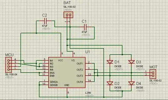
For the purpose of explaining why a motor draws a high current while starting, use the schematic shown below provides a simple explanation. The motor consists of a resistor and a generator that generators a voltage that opposes the supply voltage. The voltage is proportional to speed. When the speed is zero, the opposing voltage is zero and the current is high. As the speed increases, the opposing voltage increases and causes the motor current to decrease.

That diagram would apply best to a permanent-magnet DC motor, but it should serve well enough for an induction motor in this context.

The actual light dimming can be explained as the high current starting the motor briefly overloading the supply. Alternatively, you can include wiring resistance and a light in the schematic.

enter image description here

For a more comprehensive equivalent circuit, refer to my answer to: When load increases in rotor of induction motor how does stator draws more current?

The equivalent circuit for one phase of a three-phase induction motor is presented there. It contains the expression Rr(1-s)/s that is a resistance representing the mechanical load driven by the motor.

In that expression s is the motor's slip, the difference between the speed of the rotating magnetic fields and the relative speed of the rotor. When the motor is switched on, the rotor speed is zero and the speed of the magnetic fields is 1, so the slip is also 1 and the portion of the circuit representing the mechanical load has zero resistance. That means that the remainder of the circuit determines the current. That represents a low impedance, so the initial current is high.

As the motor speed increases, the value of s reduces from 1 to about 0.03. That results in a higher resistance that reduces the motor current, but absorbs most of the electrical power that is transferred to the motor from the source.

The results on analyzing the equivalent circuit for one phase of a three-phase induction motor are simply multiplied by three for a three-phase motor. The equivalent circuit for a single-phase motor includes two such circuits, but the two circuits are not identical. However the general principal is the same.

Here is another question in which my answer uses a more simplified version of the equivalent circuit for a three-phase induction motor: Why does an induction motor draw more current when the load is increased?

  • I like this answer because the question is reduced to that of understanding how a compressor works (as opposed to how a refrigerator works). However, I'm skeptical of your circuit diagram. Can you tell us what mean by the variables $k$ and $s$? – Michael Levy Feb 08 '20 at 14:16
  • Question: By $R2$ do you mean Rotor resistance, which is given by $R_r'$ in https://en.wikipedia.org/wiki/Induction_motor#Steinmetz_equivalent_circuit ? – Michael Levy Feb 08 '20 at 15:34
  • I have revised my answer to cover points discussed in comments. I will delete the comments. Please delete your comments to the extent that my revised answer covers them –  Feb 08 '20 at 19:22
0

A compressor has a motor and the motor is attached to a load that has torque that has to be overcome to get it to rotate because of the piston compressing on each rotation. From this site:

enter image description here

Once the motor starts rotating at a reasonable speed, the inertia of the parts helps overcome the torque as the piston compresses the refrigerant, but as it is getting up to speed there is a large current draw. That causes a voltage drop in the wiring and would possibly cause the circuit breaker to open if it continued (say if the compressor was stalled).

Lights may be more sensitive to voltage than you would expect from the voltage drop, for example a 10% drop in voltage may cause a very visible drop in light intensity.

As far as a model goes, you could model the system mechanically with SPICE. The motor current draw is strongly dependent on the RPM (because of back-EMF) so it draws maximum current when stalled. The motor torque is approximately proportional to the current draw. And the compressor could be modeled with the above torque angle curve. So as the motor-compressor combination winds up from start there would be large pulses of current that quickly increase in frequency and simultaneously get smaller as the motor gets to speed.

Note: I don't think domestic fridges have an unloader, but larger A/C units and larger air compressors typically have a valve that relieves the compression until the motor and compressor parts get moving. Maybe someone can correct me if that is wrong.

Here is an interesting video of the internals of a fridge compressor.

Usually the light dimming issue is not noticeable because the fridge is on a different circuit than the lights. The DIY SE would have more to say about those considerations.

Spehro Pefhany
  • 376,485
  • 21
  • 320
  • 842
  • In addition to the citations herein, an encyclopedic source of information appears to be found in https://en.wikipedia.org/wiki/Induction_motor. I believe that therein is a term called slip, which seems to capture much of the information being conveyed herein. @Spehro Pefhany , would you agree that the slip changes with time as the motor turns on? That when the motor is initially turned on the slip is equal to one? And that as time goes by and the motor approaches the target speed the slip approaches zero? – Michael Levy Feb 08 '20 at 14:29