1

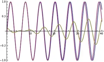
I have a differential manchester data stream (channel1) in the form of packets. I'm showing a capture of one packet. All packets begin with a stream of 1's. This is key, as per Maxim application note 3671: "

This circuit functions well when the received data stream has enough extra bits at the beginning of a packet or frame (in the form of a preamble or synch pattern) that it can afford to lose while the R1-C4 circuit charges up to the correct slicing threshold.

It is then suggested a fundamental data slicer can decode manchester encoded signals.

I need to convert this to to something an arduino, etc. can work with. scope output
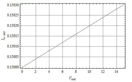
So I built the data slicer and tried various R and C value. I get a waveform as shown in channel 0. I need to obviously change my circuit, but will the fundamental circuit even get the job done?

circuit diagram

Other Information:

This is a follow up to this question. This user stated in a comment:

It is trivial to make a Manchester decoder from simple logic and 3/4 1shot.

I think he is referring to a "one-shot multivibrator op-amp circuit", with specific voltage cut-offs?

UPDATE
This FCC filing shows the schematic for reading and writing the DeLaval Alcom bus. I have reproduced my version below minus the protection portion. Alcom receive circuit
  • Data slicers do actually work and so what is your real question? – Andy aka Jan 29 '20 at 16:17
  • 1
    Recognize that the *data slicer* as shown in the OP schematic, and a *Manchester decoder* should likely be considered as **two separate circuits**, and not combined. Using a LM358 opamp as data comparator isn't recommended - a LM393 might substitute. You also might consider shortening **R1C1** time constant somewhat...is there a reason for waiting about a second for it to settle before good data gets sliced? – glen_geek Jan 29 '20 at 16:35
  • very useful comment glen_geek. I changed the RC time to something more reasonable, I was that far off the rails because I was working through different RC values to try and get some change in the output. Basically the op-amp is the problem. I have ordered a LM2903N and will try it with that. – David Sindar Jan 29 '20 at 20:22
  • 1
    This demonstrates not only the comparator is unnecessary as all you need is a simple self-biased logic inverter and the "simple" 3/4T one-shot clock recovery solution http://tinyurl.com/rzqka9w which I indicated in my previous answer. but is in fact a demo of transmitting random data in bi-phase then decoding it and comparing them. – Tony Stewart EE75 Jan 29 '20 at 21:28
  • Tony, That link is very clear. I wish I had of had that link in the previous question. The link shows the best solution with clock recovery. I don't understand "the comparator is unnecessary", are you saying that the fundamental data slicer solution will not work to get a basic output? I agree it is inferior to 3/4T one-shot clock recovery. – David Sindar Jan 29 '20 at 22:12
  • There are many good ways to limit analog data which does not demand that it be a comparator. Causing excessive startup time is not one of them. – Tony Stewart EE75 Jan 29 '20 at 23:51

2 Answers2

1

The articles talk about a comparator. LM358 is an op-amp, not a comparator. In general, op-amps work extremely poorly as comparators.

Justme
  • 127,425
  • 3
  • 97
  • 261
  • The op-amp is the reason for the poor output. A LM2903N comparator has been ordered and should work. The RC values will be changed as well to something on the timescale of micro seconds. As per calculator: (https://www.digikey.ca/en/resources/conversion-calculators/conversion-calculator-time-constant) – David Sindar Jan 29 '20 at 20:29
  • This is neither the problem nor does it state a solution. The real problem is the RC duration is >>>T= 1/bit rate when it should be around 15~20T. – Tony Stewart EE75 Jan 29 '20 at 21:27
1

that --- 1Meg Ohm and 100 uf --- is a 100 second time constant.

Also the (Ibias * 1Meg Ohm) may not been suitable.

analogsystemsrf
  • 33,703
  • 2
  • 18
  • 46