2

So I have this project, the goal is basically to be able to make a motor move to rotate a set of gears and move a panel attached to a hinge to a desired angle. I have a motor encoder attached to the motor: (https://www.amazon.com/gp/product/B07LG18HBL/ref=ppx_yo_dt_b_asin_title_o00_s00?ie=UTF8&psc=1).

I have it hooked up to an Arduino/Motor Shield like so (please excuse the terrible wiring, this is just a proof of concept): Excuse the horrible wiring job, this is just a proof of concept

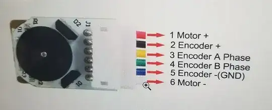
The configuration from the Motor Encoder is the following:Motor Encoder configuration

The biggest problem I'm having is that this system needs to control a system on board a satellite, so I need the motor to move to a desired angle based off a numerical input from earth. Once I get it to move, I know how to code it to the angle desired, but I'm struggling to get it to move at all right now. Do I need a separate power source for the motor? How should I code it in Arduino such that it rotates forward/backward an inputted value? There's not a whole lot of documentation on moving motors without a second encoder so I've been struggling a lot to figure this out. Any help would be much appreciated, thanks!

Keltq
  • 21
  • 1
  • `I'm struggling to get it to move at all right now` ... you really need to revise your post ... the encoder portion of your post is irrelevant if the motor remains motionless – jsotola Jan 28 '20 at 16:55
  • 1
    You should step back and consider your high-level requirements. There are many types of motors and encoders, you may not have chosen the best for your application. This encoder is a relative encoder, you need some something to determine the absolute position. An absolute encoder could be used in conjunction with this encoder or instead. – Mattman944 Jan 28 '20 at 17:00
  • 1
    Once you get everything working, simplest way is to adjust your PWM so that Duty Cycle % = Error * [Gain Factor] = [Current Position - Desired Position] * [Gain Factor]. PI, PD, and PID algorithms build up on this by adding terms that use the derivative and/or integral of the positional error. – DKNguyen Jan 28 '20 at 17:06
  • 1
    In addition to the problems already noted, in space no one can hear you scream. Which you will, once you realize that all of your moving parts have vacuum welded themselves together. And grease outgasses which both dries up the grease and contaminates everything around it. So once your brushes, gears, and journal bearings all vacuum weld themselves together, or stop moving because the grease has dried out, the remaining volatiles in the grease will deposit themselves over everything *else* in the satellite. – TimWescott Jan 28 '20 at 20:30

2 Answers2

3

Firstly, you're not going to get the motor to do much as it's configured at the moment. There are places on the terminal block for an external power supply, that will by default also power the Arduino through the Vin pin in the header - which is connected to the power jack on the Arduino board - there's a Vin cut-to-disconnect pad on the underside of the board to allow higher voltage at the motor than the Arduino likes. You can in theory power the motor shield from the Arduino's power jack, so long as the current and voltage aren't that high. What you can't do is power it from the USB socket - there's a regulator between the USB power line and the Vin line.

To use this as a servo, with control on position, you need to be monitoring the encoder, and count pulses that correspond to the rotation of the shaft. With the 150:1 gearbox and the encoder producing 7 pulses per revolution of the motor, you get one pulse per .34 degrees, or 1050 pulses per revolution. There are two channels in quadrature, so you can detect direction, but that probably isn't important for this, since the rotation is going to be determined by the polarity of the applied voltage on the motor.

Since this is a DC motor, applying voltage across the brushes will give continuous rotation, at a speed roughly proportional to the voltage - so if you know that you need to rotate through a specific angle, and count pulses, then cut power to the motor, it'll overshoot, so then you need to put in some deceleration, achieved by ramping down the PWM as you approach the target position.

Arduino's default PWM frequency is only about 500Hz, it'll work with a DC motor, but be annoyingly buzzy, and that reflects in torque pulsations on the shaft, that'll cause gear chatter. There are libraries that allow use of higher frequencies. I'm not sure if you'll find any sketches written for this particular use, but you may find something similar that you can use as a start.

And finally - why are you using cheesy hardware like this for a space application? Brushed motors aren't even used in aviation - the lack of air and especially the water vapor means that the ionized gas layer that is under a lot of the brush surface isn't present to carry current, and the chemistry isn't there to deposit the film on the commutator, so it'll wear very rapidly. Or is this just a demonstration of the principle?
Phil G
  • 5,609
  • 1
  • 10
  • 18
  • 500Hz may be bit buzzy, but it's ten times higher than standard rc servo frequency (50Hz). And as they say - in space no one can hear you scream. Of course it's not actually going into a space application - this is just a 'proof of concept'. – Bruce Abbott Jan 29 '20 at 01:50
  • 1
    Wanted to chime in, rc servo PWM frequency is NOT 50hz. The *position setpoint* of an RC servo is updated with a variable duration pulse at 50hz; the actual PWM frequency used to modulate the effective motor voltage is much higher. @Phil G is correct in questioning the choice of 500Hz PWM frequency, this is quite low and potentially dangerous on a brushed motor (gear chatter, torque ripple, brush fatigue) – Ocanath Jan 29 '20 at 18:16
1

The wiring is sort of described in the limited manual for the motor shield. https://docs.rs-online.com/cafb/0900766b816c20f3.pdf Or in this instructable: https://www.instructables.com/id/Arduino-Motor-Shield-Tutorial/

Two of the top most results from a google search on arduino motor sheild. And read up on PWM (in either the datasheet for the avr-controller on the Arduino, or in a tutorial for the arduino PWM. The arduino IDE provides examples for this if I remember correctly.

I also suggest to google servo and "servo-controller" as this is what you are making.

Bernie Nor
  • 319
  • 1
  • 6