1

I'm trying to connect a PT100 thermo probe to an Arduino project to measure water temperature. After some research I have found and adopted a design using a Wheatstone bridge and an instrumentation amp, attached below. Using this arrangement I get 0V at the output @ -15°C and 3.3V (Vcc for the Arduino) @ 125°C, which is perfect for my application.

However, the temperature probe is designed to be disconnectable, which would create floating inputs. How could I alter the schematics to make sure that when the sensor is disconnected the differential inputs are at the same voltage, so the output also reads 0V?
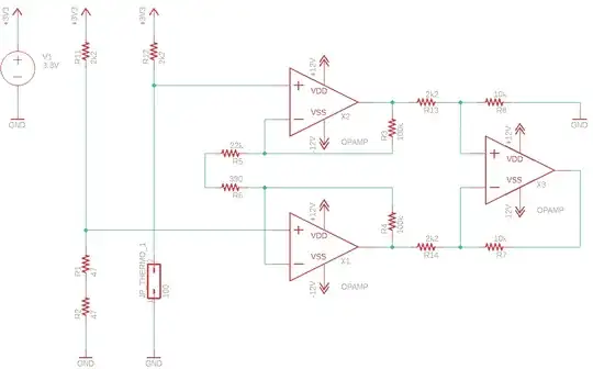
Schematics

Bolo
  • 13
  • 2
  • I would use a connector that does that similar to how an audio jack or DC barrel jack flips a mechanical switch when something plugged in for detection – DKNguyen Jan 26 '20 at 21:38

2 Answers2

0

The easiest way is to deal with it in software - the reading with the sensor disconnected will be higher than any normal reading (the resistance is infinite). Catch that measurement and convert to whatever output you need.

Kevin White
  • 32,097
  • 1
  • 47
  • 74
0

You need to protect the Arduino input by clamping the output voltage of the amplifier at an acceptable level. You may be able to do this with a couple diodes and resistor, or it might take more, it depends on a number of factors. As it sits, your amplifier can output from -12 to +12 or a bit less, depending on the op-amps.

Once you have it in digital form (it will be overrange for open-- +10V or +12V) you can have the input interpreted as you like. Usually we would prefer to have it either interpreted as an error (shut down the controller) or as overrange in a heating-type thermal system so the heater shuts down, but there are always exceptions.

Spehro Pefhany
  • 376,485
  • 21
  • 320
  • 842