2

I recently started studying electronics and I have been recently studying transistors, and I didn't quite get the spiel to these kinds of problems where you have to find its operating point. I don't know where it's best to start, what equations to write, what not to write, etc.

If someone could help me with this scheme and also some explanations and tips. It will be very appreciated.

schematic

simulate this circuit – Schematic created using CircuitLab

\$ U_{BE}=0.6V\$ and \$\beta_0 = 100\$

C. Cristi
  • 123
  • 6

2 Answers2

3

This circuit solution is known as (BJT) differential pair, (BJT) differential amplifier, long-tailed pair, emitter-coupled pair... It has two inputs - the T1 and T2 bases. The input voltages are applied between the bases and ground; hence the name "single-ended voltages". The circuit amplifies only the difference between them (differential mode) but does not react to their average value (common mode). For example, when we want to measure the voltage across a "floating" element (that is not connected to ground), we are not interested in the voltages of its two terminals relative to ground but only of the voltage across it.

Structure. This behavior is achieved through an exotic circuit trick - by pairing two "common-emitter" amplifying stages. Their emitters are joined (hence the name emitter-coupled pair) and work on a common element with high resistance (hence the name long-tailed pair). So, to understand the meaning of this odd connection, you should understand very well the behavior of the single common-emitter amplifying stage.

> Common-emitter stage with fixed emitter voltage. In this configuration, we drive the transistor by applying the input voltage to the base. If the emitter voltage is fixed (the emitter is connected directly to ground or to a constant voltage source), the whole input voltage will be applied to the base-emitter junction (the transistor input) and we will achieve a maximum gain. So, the first conclusion is - fix the emitter voltage if you want a maximum gain.

> Common-emitter stage with "loose" emitter voltage. If we connect the emitter through a resistor to ground, then the emitter voltage will be not fixed but will change in the same direction as the input base voltage. This is because the transistor passes its output (collector) current through the resistor and "creates" a voltage drop across it that changes in the same direction as the input voltage. The problem is that we change the circuit input voltage at the base with the purpose to change the transistor input voltage across the base-emitter junction... but the transistor opposes our efforts by changing its emitter voltage in the same direction. This phenomenon is known as emitter degeneration and is a kind of negative feedback. The higher the resistance in the emitter, the stronger the effect ... and if we replace the resistor with the so-called "current source", it becomes maximum... the amplifying stage does not amplify. So, the second conclusion is - "loose" the emitter voltage if you want a minimum gain.

The general conclusion is: If you want to maximize the gain, fix the emitter voltage; if you want to minimize the gain, "release" it. This is what is done in the differential pair by pairing the two transistors.

Operation. The differential pair has different behavior depending on the operation mode:

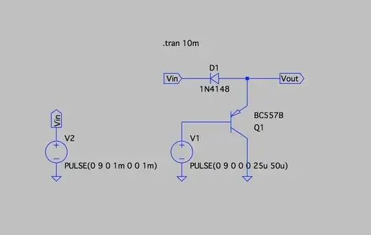
> Biasing (the OP's circuit represents this mode). First, an appropriate initial value of the emitter current must be set so that the transistors are in active mode and the output voltages are set in the middle of the operating range. This operation is known as biasing... and the OP's circuit diagram shows exactly this situation. Let's explore it in more detail because it is quite unusual here.

This procedure simply means to add another input voltage with constant value to the true input voltages that can vary during the circuit operation. The classic bias technique implies to apply the bias voltage/current in series or parallel to the input sources. Here it is made in a more clever way, from the side of the emitters by changing the value of the emitter current. We can see how on the OP's circuit diagram.

To control the transistors from the side of the emitter, the base voltages are fixed to zero by connecting the bases through 100 k resistors R1 and R5 to ground. The common emitter voltage has followed the input voltages with a small difference of about 0.7 V below.

The emitter current source exploits the inherent property of the transistor to keep its collector current constant when the input current/voltage is constant. So, it is just a transistor with a base resistor, i.e., a common-emitter stage with fixed (at -15 V) emitter voltage. The base resistor R6 sets the base and accordingly, the collector current that is actually the common emitter current of the differential pair.

Now the most interesting part of our explanation - adjusting the operating point. To adjust the bias current and accordingly, the operating point (as it is asked in the OP's question), we should vary the resistance of R6. This will make T3 change the emitter current of the pair. T1 and T2 will respond by adjusting their base-emitter voltages so that to pass the T3 collector current (negative feedback). As a result, T1 and T2 convey (each of them 1/2) the emitter current upwards to collector resistors R3 and R4. So, T1 and T2 can be thought as 1/2 bias current sources that create initial voltage drops across R3 and R4. As mentioned above, these drops should be set somewhere in the middle between ground (0 V) and the positive rail (+15 V). This procedure is known as adjusting the operating point.

So you can think of your electronic circuit as of this electrical equivalent circuit:

Asymmetrical pair visualized

> Amplifying. After the circuit is properly biased, we can apply the input voltages. In the OP's circuit, the input voltage sources are not shown. We can connect them in parallel to the base resistors R1 and R5 (directly or through capacitors) or insert them between the resistors and ground... or to remove the resistors at all... but it is important to ensure paths for the input bias currents. Why?

T1 and T2 not only adjust their base-emitter voltages according to the emitter current drawn by the current sink; this is accompanied by the flow of corresponding base currents (IC/beta). So, the negative feedback forces the transistors to sink these currents from the ground through the base resistors... and these currents should pass in some way. This is the role of the resistors - to ensure paths for the base currents if the input sources are not galvanic.

At differential mode, the input voltages change in opposite directions. The common emitter voltage is fixed in the middle between the input voltages since the transistors "pull" the common emitter point in opposite directions (like in tug of war or arm wrestling). The collector currents vigorously change (steer)... the output (collector) voltages vigorously change in opposite directions... and the gains are maximum.

At common mode, the input voltages change in the same direction. Both transistors act as one compound common-emitter stage with a current source in the emitter. So, the common emitter voltage follows the input voltages and the gains are minimum. The output (collector) currents and voltage drops across collector resistors do not change.


Finally, here are some specific recommendations for calculating the circuit. You can think of T1 and T2 as current sinks drawing 1/2 bias currents from the resistor network R2, R3 and R4 (see the picture above). The currents actually go to the negative power supply but here, for simplicity, I closed them to ground. R3 and R4 should be equal; then R2 will not influence the output voltages. I suppose that R4 is deliberately made different to show the error introduced by such an asymmetry.

Circuit fantasist
  • 13,593
  • 1
  • 17
  • 48
  • 1
    Mmmhh...I am not tooo happy with this explanation because - when the common emitter voltage is "fixed" - we have no explanation for the fact that an input at T1 influences also the output of T2. We should not forget that in parallel to the "large" emitter resistance the small input resistance of the T2 is. And this applies , of course, from the other side also (input at T2). To me, the best explanation is: The diff. pair can be seen as a common collector (emitter follower)-common base combination. This view immediately allows the correct gain calculation as well. – LvW Jan 21 '20 at 16:57
  • I have described the case of a differential input signal where both input voltages change with the same rate but in opposite directions. In this fully symmetric configuration, the common emitter point has constant voltage and the two stages act as common-emitter stages with a constant voltage source in the emitters. Your explanation is valid for the asymmetric configuration where the one of bases is fixed and a single-ended input voltage is applied to the other base (aka "emitter-coupled amplifier"). The calculation is the same as of the single common-emitter stage with fixed emitter voltage. – Circuit fantasist Jan 21 '20 at 17:10
  • 1
    Ahh - OK, I see. Of course, in this case, the emitter potential remains constant. Thanlk you for clarification. – LvW Jan 21 '20 at 19:37
  • _"This circuit solution is known as (BJT) differential pair, (BJT) differential amplifier, long-tailed pair, emitter-coupled pair"_ Sorry but it is _not_ a differential pair. It might resemble one but it's isn't. – edmz Jan 21 '20 at 19:46
  • @edmz, Just because R3 and R4 are different? – Circuit fantasist Jan 21 '20 at 21:01
  • Absolutely. It's one of the key ingredients of what constitutes a passive-load differential pair. To me such circuit, as you correctly point out, aims to strictly amplify differential-mode signals and reject common mode ones; the way this is done is by enforcing _symmetry_ between the two branches. That's what gives you CMR/'differential amplifier' (although I tend to avoid this name). Also OP's circuit doesn't really have input terminals, unlike DPs. – edmz Jan 21 '20 at 21:41
  • @edmz, Of course, I am also puzzled by this significant asymmetry and I can only guess why it is so (maybe it is deliberately done). Regarding the input terminals, they are not shown because the purpose of this arrangement is to consider only the biasing by the emitter current source. The inputs are connected through 100 k resistors to ground to close the paths of the input bias currents. As I have described, the input sources can be inserted between resistors and ground (if they are galvanic) or connected in parallel to the resistors (directly or through decoupling capacitors). – Circuit fantasist Jan 21 '20 at 22:22
  • 1
    @edmz, what is a differential amplifier? I think, it is an amplifier that reacts upon the difference between the two input signals - and amplifies it. Correct? Of course, for the shown circuit the diff. gain values are different at both collectors - nevertheless, in both cases the input diff. voltage is amplified. Hence, the shown structure is a diff. amplifier. However, it does not work for the shown parts values - but that is another question. Remember, that in some cases the collector resistor is even zero - nevertheless, the other collectors output signal is the amplified diff. signal. – LvW Jan 22 '20 at 09:20
  • @LvW: When I read 'differential amplifier' I (personally) think of the op amp voltage subtractor [this one](https://www.electronics-tutorials.ws/opamp/opamp_5.html) aka diff. amplifier. That's terminology if you will, but that's the one I reckon as most correct. – edmz Jan 22 '20 at 20:45
  • @LvW: For the second part. A differential amplifier has to have high midband CMRR, otherwise you cannot call it as such; that's what defines it as such. The only way to establish good CMRR is symmetry and maybe CMFB, clearly all to be done when still handling double-ended signals. Also the differential gain of a passive-load differential pair is largely determined by collector resistors, so what you've said is nonsense. – edmz Jan 22 '20 at 21:00
  • 1
    @edmz, Please, stay with a technical discussion without getting polemical ("nonsense"). That does not make a good impression. Yes, we are interested in a high CMRR. But no diff. pair (with BJTs or opamps) has an infinite CMRR. Yes, we want as much symmetry as possible. But when you refuse to call the shown circuit "diff. amplifier" - do you have a CMRR limit in mind ? Such an amplifier with a CMRR below 40dB or 60 dB - is it in your definition not a diff. amplifier? Such a limit is very arbritrary. In each textbook you can find a long-tailed pair with only one coll. resistor. Nonsense? – LvW Jan 23 '20 at 09:25
  • Perhaps this misunderstanding comes from the fact that here we are limited to a differential pair with a differential output (fully differential amplifier). The meaning of the emitter current source is best seen when the output is single-ended... where indeed one of the resistors becomes redundant. – Circuit fantasist Jan 23 '20 at 10:12
  • @LvW, I did not intend to be polemical or offensive anyhow, sorry if that might have sounded like so; my statement was about objectively ('circuitally-speaking' if you wish) replying to what you said. It is _not_ that if X circuit has CMRR > 40dB is a diff. amplifier but then at 39dB it isn't. Rather, the point here is that my initial statement was 'to me this circuit is not a differential pair'. We give circuits name because they implement very specific design aspects, not for fashion or arbitrariness. To be clear, I'd have said the same if (say) there were a 2N2222 and a 2N4401 instead. – edmz Jan 23 '20 at 20:00
2

First of all, learn from a good design rather than this one.

This answer will not "spoon feed" you how to learn, rather, what to learn. Your circuit has some reliable clues, that it is a terrible design and the first and most important, is that it has no "specs." or "expectations in writing" as I like to say.

Typical Amp. Specs:  @ +/-15V 25'C
-------------------------
Purpose:       LF Pre-Amp 
Impedance, Zin:  ___ Min,   ___ Max
Output swing Vo: ___ Min
AC  gain, G:     ___ Min,   ___ Max
Idle current:    ___ Max  Vcc, ___ Max Vee 
Impedance  Zout: ___ Max (1kHz)   depends on AC Gain
Input Offset Vio:___ Max          with 10% mismatch on hFE
Input       Vcm: ___ Min ,  ___ Max
Input Bias, Iin: ___ Min,   ___ Max     
Bandwidth        ___ MHz , depends on GBW /G of  Q1,Q2
Distortion  THD: ___ Max , at 1kHz full swing.

Now all you wanted to know was the DC Q points. The biggest variable here is DC bias current below the emitter pair and every resistor is a poor choice. R6 ought to be 1.5 MOhm but still no gain. Let's not solve this design.( and say we did)

The controlling resistor is R6 as you have unwisely tied the emitter to Vee. I(R6) determines the Q point of every node.

Ic3=hFE*(Vee-0.6)/R6 for T3. Choose <1mA. From that, everything else can be determined.

What you should learn is how the most amazing Op Amp (OA) the uA741 works for each stage. Once you appreciate it's mastery, try some modern OA's. Learn to appreciate specs in datasheets then working on a single supply or with inputs working to the lower negative rail with PNP inputs at 0V. Then look at the CMOS FET OA's that go Rail-2-Rail on outputs like CMOS logic except linear.

So here is the crappy amazing interactive 741. (in slow motion)

enter image description here

OK give up?

How do choose the best Q points for this configuration?

Step 1

Make a list of desirable but reasonable expectations. "A Good Spec." ( do exactly the same when looking for a partner and advertise it.) seriously!

Typical Amp. Specs:  @ +/-15V 25'C
-------------------------

Purpose: General Purpose Pre-Amp

Impedance, Zin:  100k Min,   ___ Max
Output swing Vo: 10Vpp Min
AC  gain, G:     100 Min,   ___ Max  250 maybe poss. compromises Output swing, Zin
Idle current,Icc: (Vcc/Rc)  10uA  Max  Vcc, 12uA Max Vee 
Impedance  Zout:  2M  Max (1kHz)   depends on AC Gain
Input Offset Vio: 1mV Max          with 10% mismatch on hFE
Input       Vcm:   0V +/-12 
Input Bias, Iin:    1% Icc   
Distortion  THD:    1% Max , at 1kHz full swing.

schematic

simulate this circuit – Schematic created using CircuitLab

\$ U_{BE}=0.6V\$ and \$\beta_0 = 100\$

In order to make a CC sink T43 is added with very low current so 0.6V drops to 485 mV.

Now ask some intelligent questions to impress your partner.....then listen...

Tony Stewart EE75
  • 1
  • 3
  • 54
  • 182
  • In places , tongue was pressed firmly in cheek. – Tony Stewart EE75 Jan 21 '20 at 23:47
  • Compare with your simulator http://tinyurl.com/utha8c4. I like Falstad. – Tony Stewart EE75 Jan 22 '20 at 06:19
  • 741 simulation? Wow! Fantastic... This is already a serious game with many players... My grandson will ask me what is this new game:) – Circuit fantasist Jan 22 '20 at 07:11
  • T4 looks like an "active diode" to me... providing reference voltage to the T3 current sink. The voltage type negative feedback for T4 is closed through the emitter follower T3. Intertwined connections... remind me the Wilson current mirror... – Circuit fantasist Jan 22 '20 at 07:25
  • No it's Bob Widlar's current source (sink actually) @Circuitfantasist https://en.wikipedia.org/wiki/Bob_Widlar\ – Tony Stewart EE75 Jan 22 '20 at 07:31
  • Hmmm... I think it's not exactly the Widlar idea since the T4 base is not directly connected to its collector but through the T3 base-emitter junction. This is a more sophisticated solution than the classic Widlar current sink: T3 emitter follower closes the T4 feedback to make it act as a "diode"; then T4 "diode" provides reference voltage for T3 emitter follower to make it act as a current sink. Who invented this beauty? – Circuit fantasist Jan 22 '20 at 09:03
  • This is exactly Widlar's brilliant patent. Go read. It has a huge advantage over the Wilson when you want to reduce Ic/Ib by hFE*hFE instead of just hFE as in the case of the Wilson Current Mirror. @Circuitfantasist As result of the overdrive as R7/R4 is just over 100 instead of 10k , The 10uA current sensitivity to Vee -2 to -20V is far less than the Wilson and does not need such a high R7 to achieve 10uA. Yet even more stable is a CC to bias R7 which is also his idea. – Tony Stewart EE75 Jan 22 '20 at 15:00
  • Is there no one to appreciate this hard work? Is it customary to make such simulations of known ICs for free? For me personally, this is something invaluable and I will research it in detail to adjust some of my notions about the internal structure of the op-amp... – Circuit fantasist Jan 23 '20 at 10:20
  • 1
    Those who appreciate are silent. I learnt when I was a young student who graduated in '75 and now is like riding a bicycle. I am sure others appreciate but EE's are not known to praise. – Tony Stewart EE75 Jan 23 '20 at 12:55
  • Maybe this is more appropriate for the meta section, but let's just say it here... I can understand these young people asking questions... and forgive them the lack of attitude they sometimes show to the authors of the answers... but I cannot understand the lack of attitude in peers. Each of us does a great deal of work to answer questions... and invests a lot in this... and it deserves the encouragement. It's like a greeting that costs us nothing but means a lot to others. I wonder if there is a place on the web where frank discussions are held and participants are encouraged by each other... – Circuit fantasist Jan 23 '20 at 14:56
  • I suggest you ask in Meta if Admins are interested in raising a culture to elevate this. @Circuitfantasist If it does get direction from our brilliant admin Dave and others, this site will go downhill. A verbal chatroom is needed for better communication. – Tony Stewart EE75 Jan 23 '20 at 15:21
  • Tony, What is the name of this 2-transistor source in the emitters? Who invented it? I have not found confirmation of your thesis that Widlar is the inventor of this structure. Indeed, it was used by him in the current protection of the output stage of his 702 op-amp. I ask you since I have managed to reveal the basic idea behind this clever topology and now I am preparing a question & answer about it... – Circuit fantasist Feb 05 '20 at 12:30
  • https://books.google.ca/books?hl=en&lr=&id=03JmxpE39N4C&oi=fnd&pg=PP1&dq=info:u1Z6KSIeFXYJ:scholar.google.com/+&ots=5yioF1YlEa&sig=Yov6AgMmRVuDHbKjc8JB6guwJis&redir_esc=y#v=onepage&q=widlar&f=false not hard to find – Tony Stewart EE75 Feb 05 '20 at 15:41
  • Thanks... but there is no exactly such solution. There is a similar circuit of current mirror with an emitter follower in the feedback loop of the input transistor (Fig 4.24, page 78). – Circuit fantasist Feb 05 '20 at 16:10
  • Tony, I kept my promise and asked the question - https://electronics.stackexchange.com/questions/483339/what-is-the-idea-behind-the-ingenious-widlar-current-limiter. Would you join the discussion there? I think it will be interesting for you to unravel the secret of Widlar... – Circuit fantasist Feb 26 '20 at 21:25