First of all, analyzing an AC circuit with purely real ohmic impedances is just as straight forward as analyzing a DC circuit, you just let neutral be ground, and use the RMS voltages and currents as if they were DC values.
In your case you have four basically different circuits, because you have three circuits where one of the terminals are disconnected, these are all unique, and three circuits where all three terminals are connected to some voltage source with the same reference. This means that we need to solve four different circuits individually to find the solution for each configuration.
I will leave "Open Line", "Open Neutral" and "Open Earth" for you to solve, this should be easy now that you know that you need to solve all these three individually.
However it might not be obvious to you how you can solve the remaining three in one go, so I will go ahead and give you a hand.
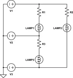
simulate this circuit – Schematic created using CircuitLab
In the schematic above I have made an abstraction, and avoided thinking of the three terminals as being connected to either line, neutral or earth, and just thought of them all as connected to arbitrary voltage sources V1, V2 and V3, this allowes me to solve the circuit ones, and then substitute the voltage values afterwards to find the final solutions.
When we solve circuits with multiple sources we use the principal of superposition, which to put it in short terms, means that we calculate the voltages and currents that we are interrested in as a function of each source individually, and then we add those results together in the end to get the final solution with all the sources acting on the circuit. This is always valid to do if your cirucit is linear.
For voltage sources, when they are not part of the particular solution being calculated, they are shorted. So to calculate the solution we get with only V1 we do as follows.
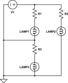
simulate this circuit
Let's reference the currents in all the resistors in the direction going from the top to the bottom of the diagrams, and let's reference the voltages accordingly, going from the top down, I will call the currents in the resistors I1, I2 and I3, to denote the currents in resistors R1, R2 and R3.
In the diagram above, where we only considder V1, the currents are as follows;
$$I_1=\frac{V_1}{R_1}$$
$$I_2=\frac{V_1}{R_2}$$
$$I_3=0$$
Now the diagram drawing tool is really cumbersome, so I wan't draw all the diagrams, but the soluting when considdering V2 and V3 are:
$$I_1=-\frac{V_2}{R_1}$$
$$I_2=0$$
$$I_3=\frac{V_2}{R_3}$$
$$I_1=0$$
$$I_2=-\frac{V_3}{R_2}$$
$$I_3=-\frac{V_3}{R_3}$$
Now we add the solutions together:
$$I_1=\frac{V_1}{R_1}-\frac{V_2}{R_1}$$
$$I_2=\frac{V_1}{R_2}-\frac{V_3}{R_2}$$
$$I_3=\frac{V_2}{R_3}-\frac{V_3}{R_3}$$
Above is the final solution of the KVL/KCL analyzis, for the three circuits where all terminals are connected.
Now to find the particular solutions for the three individual configurations we just substitute V1, V2 and V3 with the voltages of the terminals that they are connected to, for this purpose we considder neutral and earth to both be at 0V, and line to be at Vl.
Line/Earth Reversed
$$I_1=\frac{0}{R_1}-\frac{0}{R_1}=0$$
$$I_2=\frac{0}{R_2}-\frac{V_l}{R_2}=-\frac{V_l}{R_2}$$
$$I_3=\frac{0}{R_3}-\frac{V_l}{R_3}=-\frac{V_l}{R_3}$$
Line/Neutral Reversed
$$I_1=\frac{0}{R_1}-\frac{V_l}{R_1}=-\frac{V_l}{R_1}$$
$$I_2=\frac{0}{R_2}-\frac{0}{R_2}=0$$
$$I_3=\frac{V_l}{R_3}-\frac{0}{R_3}=\frac{V_l}{R_3}$$
Correct
$$I_1=\frac{V_l}{R_1}-\frac{0}{R_1}=\frac{V_l}{R_1}$$
$$I_2=\frac{V_l}{R_2}-\frac{0}{R_2}=\frac{V_l}{R_2}$$
$$I_3=\frac{0}{R_3}-\frac{0}{R_3}=0$$
Since we are dealing with AC we don't care if the sign is positive or negative, as this just means that the AC waveform is phase shifted 180 deg, and we only care about the RMS values in this case.
If we match the solutions above with your original truth-table, we see that they match up, indeed the solution gives us currents in the lamps that we are expecting.
Now as I sayed I will leave it for you to solve the remaining three where one of the terminals are disconnected, for these you need to do the same thing that I did, but just leaving the disconnected terminals floating throughout the calculations, so for example when Line is disconnected, R1 and R2, and their lamps, will be in series.


