Limit switches, unless your linear actuator already has them built in, to turn off your motor when it goes too far, and some drives relays could do this. And a button or two.
But if you want something technical and complicated then you still need those components. The Pi just reads the "trigger" whatever it may be and then drives the relays accordingly.
The relays would need to be wired up in an H-bridge configuration. The RPI pins can't supply enough current (and probably not the correct voltage either) to drive the relays, therefore you will need to drive transistors with the RPI and the transistors drive the relay coils.
As for the cue, we definitely need more info for that. Is the cue someone pushing a button? Or a person on stage making a gesture or vocal cue? They are wildly different in difficulty.
I would actually use a PICAXE for something like this, not a RPI which is massively. Massively. Overkill. That is of course, unless you expect it to do something like motion or speech analysis for the cue. But it seems that would be beyond your abilities anyways, and hardly worthwhile even if it wasn't.
I would focus on the H-bridge relay part first to drive your actuator in both directions. You need that either way and could probably slap one together in about 10 minutes if you had all the parts. Once you finish that to the point where you can manually apply signals to the relays to turn the motor in both directions, then you can focus on how to limit its motion or trigger its motion automatically.
Since you seem to have no idea what it is you need, here are some starting materials:
 https://www.youtube.com/watch?v=nMHETW-zOrQ
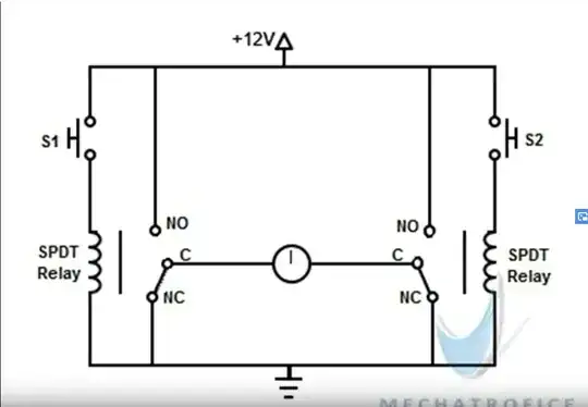
Holding one button turns the motor one way. Holding the other other button turns the motor the other way. It turns endlessly as long as you hold the button so if you want it to stop you need limit switches to disconnect the motor once it hits an end point. The linear actuator may have them integrated.
NO stands for normally open and NC stands for normally closed. Basically the default state of the relay contact when the coil is unpowered. Those relays are SPDT (single-pole, double-throw relays). Single pole because it has one path through it at any one time, and double-throw because it can switch the aformentioned path between two separate possibilities. If you can't get SPDT relays, you can use twice as many SPST (single-pole, single throw) relays instead. Single-pole because one path through it, and single-throw because it switches between one possibility for that path.
If you want to use a Raspberry Pi for this, then it will be driving the relay coils in some way based on its reading of a button. The RPI will not be able to drive the relay coils directly from its pins because it cannot supply enough current and probably not enough voltage. You will need to drive transistors (which can be driven by the RPI pin voltages and currents) to control a larger current which will in turn drive the relay coils, which will in turn control the even larger current that drives the motor.
See here: How do I energize a 12v relay coil using a 2N2222 bipolar transistor?
What if you build the two-button manual circuit I posted (you likely need to do that anyways as an incremental step if you don't know what you're doing), and then just leave it like that instead of implementing the RPI? I'd bet though that if you just built the button version and have it working then your manager will suddenly find more important things that need to be done.

