0

I am currently trying to figure out if a high frequency (GHz) resonant inductive coupling circuit would be feasible and efficient when wirelessly transferring power. Through many research papers, researchers suggest operating at frequencies lower than 100MHz.

I have seen people using two coil, three coil, four coil systems, but didn't seen anyone operating at frequencies higher than 100MHz.

Why is that the case? What are the governing laws of such behavior?
Voltage Spike
  • 75,799
  • 36
  • 80
  • 208

2 Answers2

1

I assume you are referring to WPT standards in 4,8,11,22 kW levels or small power for mobiles.

  • stray energy damage to humans increases with frequency measured in SARs mW/g this must be absorbed by careful lossy ferrite .

  • maximal energy transfer is when impedances are matched and this is far easier with lower f due to stray geometry of capacitance nad wire inductance.

  • the number of coils is an attempt to match impedances for mismatch in position orientation and reduce the max. Q in any stage which affects resulting tolerance errors
  • the mutual coupling M falls off sharply as the gap starts to exceed the diameter.

  • THus lower frequency lends itself to greater range and lower mutual coupling loss.

However there are people who believe Wifi ROuters with rapid directional beam antennae can be used for WPT at GHz range , but I think health risks are high the eyes. (caterogenic)

Tony Stewart EE75
  • 1
  • 3
  • 54
  • 182
  • I think the main limitation comes from the increase in radiation resistance that limits efficiency. The limiting factor is coil Q. M is mostly independent of the frequency, isn't it? – Pojj Dec 30 '19 at 15:06
1

Main fundamental reasons for limiting the working frequency of inductive power are

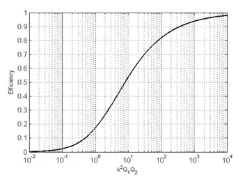
  1. The First reason is the increase of radiation rasistnace that limits the inductive link efficiency. The theoretical limit for maximum efficiency of the inductive link is given by,

    \$ \eta_{\rm max} =\frac{k^2 Q_1 Q_2}{\left(1+\sqrt{1+k^2 Q_1 Q_2}\right)^2}\$ where \$k\$ is coupling coefficient (\$k=M/\sqrt{L_1L2}\$), \$Q_1\$, \$Q_2\$ are coil quality factors (\$Q_{1,2}=\frac{\omega L_{1,2}}{R_{1,2}}\$). \$M\$-Mutual inductance, \$L_{1,2}\$-Coil inductance, \$R_{1,2}\$-Coil resistance

    The maximum efficiency variation as a function of \$k^2 Q_1 Q_2\$ enter image description here

    So, you need to maximize \$k^2 Q_1 Q_2\$ product to obtain a reasonable efficiency. Coupling \$k\$ does not vary much with respect to the frequency - it depends on the coil geometry and the distance between coils.

    The frequency limit comes from the coil quality factor. With the increase of frequency, radiation resistance of the coils become more dominant and the quality factor drops with the increase of the frequency, which limits the maximum possible efficiency. For example, quality factor variation for 3 turn coil of 10 cm radius is

    enter image description here (Source)

    What happens here is that the inductive coils begin to radiate (to far-field) with the increase of the frequency and coils are becoming more like antennas making them not suitable for near field inductive coupling

  2. The second limitation is from the high-frequency generator and power conversions. As the frequency goes high, the maximum possible power level of the power converter goes down because of the device level limitations. Also, the efficiency of power converters (both inverter and rectifier) becomes a challenging issue for high-frequencies.

  3. Additionally, as @TonyStewartSunnyskyguyEE75 mentioned, there are some practical challenges (which can of course solved by proper design) such as difficulty in tuning and meeting human exposure safety-limits.

Pojj
  • 818
  • 2
  • 10
  • 25
  • Although high Q is necessary to tune and extract high real power (the denominator) , if you want to increase the demoninator to say 80kW to charge up a bus, even IF infinite Q microwave coils existed, you would not want to use them for the reasons I stated. In fact you would go towards the lowest practical frequency just above the audio band at 20kHz .. I can link proof by examples. This is because WPT poses a real EMI threat – Tony Stewart EE75 Dec 30 '19 at 15:20
  • Of course, the practical frequencies would be in kHz region. My intention was to answer " What are the governing laws of such behavior?" I am not sure if OP is targeting high-power (80kW) at 100 MHz - if so, there won't be any practical power converter to generate 80kW at this frequency. True that EMI is also a great concern for high power (if high power is the requirement) – Pojj Dec 30 '19 at 16:37