5

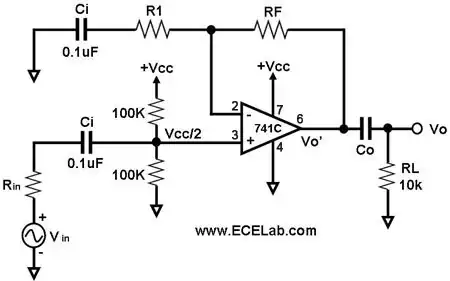
I found the following schematic here and built it to test it . . .

enter image description here

I think all the capacitors are there to just block DC, but how important are the capacitance values and how does one determine the value of Co? The source webpage only discusses gain characteristics of the circuit.

learnvst
  • 1,213
  • 3
  • 21
  • 28

1 Answers1

4

The bottom left capacitor and \$C_O\$ are coupling capacitors.

The top left capacitor acts to increase negative feedback to 100% at DC.

The capacitor values should be large enough such that there is negligible effect at the low end of the frequency band of interest.

For example, for an audio amplifier, you want to amplify frequencies as low as 20Hz. Thus, you want:

\$\dfrac{1}{2 \pi R_LC_O} << 20Hz \$

The input coupling capacitor interacts with the source resistance \$R_{in}\$. It can be shown that:

\$\dfrac{1}{2 \pi (R_{in} + 50k\Omega)C_{i(in)}} << 20Hz\$

For the feedback capacitor, it can be shown that:

\$\dfrac{1}{2 \pi R_1C_{i(fb)}} << 20Hz\$
Alfred Centauri
  • 26,502
  • 1
  • 25
  • 63
  • Thanks. Do I need to worry about the value of the capacitor on the voltage input also? Furthermore, whay is the purpose of `Rin`. Is it just an attenuator? – learnvst Oct 31 '12 at 13:55
  • 1
    @learnvst, Rin represents the *source* resistance; it's not actually part of the amplifier circuit however, it does interact with the input coupling capacitor. I'll update my answer. – Alfred Centauri Oct 31 '12 at 14:47
  • Ah, so if I know that Vin is from a microphone and I know its nominal output impedance from a data sheet, I should replace Rin with that value if simulating the circuit? – learnvst Oct 31 '12 at 14:53
  • @learnvst, that's exactly what you should do. – Alfred Centauri Oct 31 '12 at 15:03
  • @learnvst, I made a correction to the final equation. – Alfred Centauri Oct 31 '12 at 18:06
  • one more question. How would I determine the output impedance of this circuit? Thanks – learnvst Nov 03 '12 at 00:24
  • @learnvst, the load is never part of the output impedance (just as the source resistance is never part of the input impedance). So, assuming RL is the load, the output impedance of this circuit is determined almost entirely by the output impedance of the opamp. For an ideal opamp, the output impedance is zero and it is small for real opamps. To find it via simulation, zero Vin and connect a 1A AC current source in place of RL. The output impedance, as a function of frequency, can be read directly by plotting the AC voltage across the current source. – Alfred Centauri Nov 03 '12 at 13:20