3

Okay, this may be a stupid question, but at the beginning of my Applied Electronics course they taught us that the differential gain \$A_d\$ of an operational amplifier is ideally infinite; however, in real op amps, we get a limited bandwidth. Which is fine, because it's still very high. My problem raises when I was introduced to common-mode gain and differential-mode gains. In particular, I read that an amplifier subject to common-mode input signals has as a (non-ideal) output a linear combination of its differential mode input voltage mode and its common mode input voltage, i.e., $$A_dv_d + A_{cm}v_{cm}.$$ And for now, everything's fine. But let's consider the practical example in the picture below:

schematic

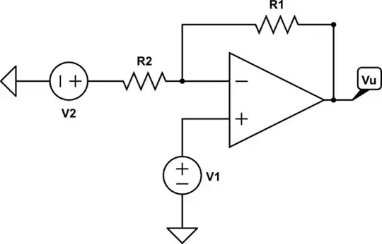
simulate this circuit – Schematic created using CircuitLab

According to what I read, in the schematic above $$V_u=(1+\frac{R_1}{R_2})(v_+-v_-)=\frac{R_1+R_2}{R_2}V_1-\frac{R_1}{R_2}V_2.$$ And since \$\frac{V_1+\frac{R_1}{R_1+R_2}V_2}{2}=v_{cm}\$ and \$v_d=v_+-v_-\$, then \$V_1=v_{cm}+\frac{v_d}{2}\$ and \$V_2=v_{cm}-\frac{v_d}{2}\$. Moreover: $$V_u=\frac{R_1+R_2}{R_2}(v_{cm}+\frac{v_d}{2})-\frac{R_1}{R_2}(v_{cm}-\frac{v_d}{2})=v_{cm}(\frac{R_1+R_2}{R_2}-\frac{R_1}{R_2})+v_d(\frac{R_1+R_2}{2R_2}+\frac{R_1}{2R_2})=\Big(\frac{1}{2}+\frac{R_1}{R_2}\Big)v_d+v_{cm}=A_dv_d+A_{cm}v_{cm}.$$ How are we even just able to say that \$A_d=\frac{1}{2}+\frac{R_1}{R_2}\$? It's limited, fine, but I would've imagined bigger numbers. I guess I can live with a common gain of 1, but since they called both differential gains \$A_d\$, are they seriously the same?

Already from the beginning, I couldn't even understand why would we use $$V_u=(1+\frac{R_1}{R_2})v_d,$$since \$V_u=A_dv_d\$, with \$A_d\$ a big value and, instead, considering an ideal op-amp, as \$A_d\$ approaches infinity, \$V_u=\frac{1}{\beta}v_+=(1+\frac{R_1}{R_2})v_+.\$ But shouldn't \$(1+\frac{R_1}{R_2})\$ be the gain from the non inverting terminal to the output (i.e., closed loop gain), not of the op-amp, or am I wrong? What am I missing? Thank you in advance!

Edit: I am starting to assume that the answer is due to the principle of superposition of effect, i.e., shutting \$V_2\$ off and compute \$Vu\$ due to \$V_1\$, and then shut \$V_1\$ off and compute the overall gain due to \$V_2\$, and adding then the two results together. This could make sense, I suppose, but I can't still figure out why the result is equivalent to \$v_d\frac{R_1+R_2}{R_2}\$, since \$v_d\$ is supposed to be very small and it should therefore be amplified by a high gain \$A_d\$.

Edit 2: fixed typo that made the result wrong, but the question still holds.

Edit 3: fixed the value of \$\beta\$ in the formulas for this schematic. Unfortunately, I chose an unconventional position for \$R_1\$ and \$R_2\$ in the schematic.

  • 1
    have you read about the "virtual ground" method of thinking about typical opamp circuits? – analogsystemsrf Nov 14 '19 at 01:54
  • Open loop gain is infinite (ideally), closed loop gain is not so. With extremely large gain, op would be + or - Vsat even with small noise.. using feedback, *you* can control gain. – Deep Nov 14 '19 at 03:33
  • I'm aware that the closed loop gain is not infinite, but shouldn't the closed loop gain be applied from the non-inverting terminal to the output, i.e., the whole circuit? I've always thought of the feedback signal being Vu times beta, the feedback gain, which is actually the voltage at the inverting terminal and then subtracting it from the input node gets v_d, which then gets amplified by Ad, giving thus the output Vu=v_+*(Ad/(1+Ad*beta)). But if that's correct, then v_d goes through Ad, not the closed loop gain – Maurizio Carcassona Nov 14 '19 at 13:31
  • I know what a virtual ground is, like when you have 0V at v_+ and due to v_d being 0, then also v_- is 0, making it a virtual ground. But I'm not sure what you mean by method – Maurizio Carcassona Nov 14 '19 at 13:33
  • 2
    \$V_u=(1+\frac{R_2}{R_1})(v_+-v_-)\$ - This relation is wrong because \$(v_+-v_-)\$ is zero here because of the -ve feedback .... – Meenie Leis Nov 14 '19 at 19:12
  • @MeenieLeis indeed, to my knowledge it's wrong as well, since an infinitesimal voltage should get an (ideally) infinite gain, i,e, I thought it should be $V_u=(v_+-v_-)A_d$, not $V_u=\frac{1}{\beta}(v_+-v_-)$. However, any example I see regarding the common gain computation leads to this result, yet I can't understand why, – Maurizio Carcassona Nov 15 '19 at 15:06
  • I can understand this result when applying the principle of superposition of effects, but the result it leads still doesn't make sense to me, when considering the circuit as a whole. – Maurizio Carcassona Nov 15 '19 at 15:24
  • 3
    You are confusing two issues. There is the differential gain of the op amp. This is a very high number, infinite in the ideal. This is the ONLY gain an op amp has. Then, there are differential gains and common mode gains for op amp circuits -- i.e., amplifiers constructed out of op amps. – Scott Seidman Nov 15 '19 at 15:30
  • Oh thanks, I got confused by the same name Ad; at least this explains its magnitude. However, considering the relation \$(v_+-v_-)=v_d\$ multiplied by something, isn't it exactly the same as the one for op-amps' gain, i,e, \$A_d: V_u=A_dv_d\$? One way I would see the gain of the circuit is to look at the closed loop gain of the fb system, which for A_d->inf is the reciprocal of the fb gain itself; but again, when applying 2 inputs, I get \$V_u=v_d/\beta\$ - and ok, conceptually \$\frac{1}{\beta}\$ is the circuit's gain, but mathematically, aren't that and the amp's held by the same relation? – Maurizio Carcassona Nov 15 '19 at 17:24
  • 1
    I have not seen in ANY books, the very first relationship you have written on Vu. You just misinterpreted it. It's simply wrong assumption you started with. – Meenie Leis Nov 16 '19 at 10:20
  • I see, so it's all due to a misinterpretation. That reassures me, because I couldn't really come up with a conclusion. Thank you all so much for the answers! – Maurizio Carcassona Nov 16 '19 at 14:06

1 Answers1

4

$$\bbox[4px,border:1px solid red]{V_u=(1+\frac{R_2}{R_1})(v_+-v_-)}$$ The above assumption where you start from is actually wrong.

\$(v_+-v_-)\$ is infinitesimaly small or zero ideally.

The correct relation is: $$V_u = a_d.v_d + a_c.v_c$$ $$ie.,V_u = a_d.(v_+-v_-) + a_c.\frac{(v_+ +v_-)}{2}$$ $$\bbox[8px,border:1px solid black]{V_u = G_{OL}.(v_+-v_-)} $$ Where \$a_d\$ or \$G_{OL}\$ is the open-loop differential gain or simply open-loop gain, and it is very big or infinite for ideal op amp. And open-loop common-mode gain \$a_c = 0\$.

Coming to closed-loop gains in your circuit:

$$V_u=(\frac{R_1+R_2}{R_1})V_1-(\frac{R_2}{R_1})V_2 \tag1$$

The circuit has a negative feedback and you can calculate closed-loop differential and common-mode gains using the relations: $$V_1 = V_c+\frac{V_d}{2}$$ $$V_2 = V_c - \frac{V_d}{2}$$ where \$V_d\$ and \$V_c\$ are differential and common-mode components of \$V_1\$ and\$V_2\$:

$$V_d =V_1-V_2 $$ $$V_c = (V_1+V_2)/2 $$

Equation (1) can be simplified as: $$V_u=(\frac{R_1+R_2}{R_1}).(V_c+\frac{V_d}{2})-(\frac{R_2}{R_1}).(V_c - \frac{V_d}{2})$$ $$\implies V_u = (\frac{1}{2}+\frac{R_2}{R_1}).V_d+1.V_c \tag2$$ Compare (2) with: $$V_u = A_d.V_d+A_c.V_c$$ $$\bbox[8px,border:1px solid black]{\therefore A_d = (\frac{1}{2}+\frac{R_2}{R_1}), A_c = 1 }$$ where \$A_d\$ and \$A_c\$ are closed-loop differential and common-mode gains respectively.

Meenie Leis
  • 2,752
  • 11
  • 28
  • Thank you! I actually made a typo for the result, 'cos I forgot to write a - for \$\frac{v_d}{2}\$. However, I still wonder: when you write \$V_u=(\frac{R_1+R_2}{R_1})V_1-(\frac{R_2}{R_1})V_2\$, since \$V_1=v_+\$ (isn't it? Maybe that's where I'm getting confused) and \$v_-=V_2\frac{R_1}{R_1+R_2}\$ (?), isn't the expression equal to \$V_u=(\frac{R_1+R_2}{R_1})(v_+-v_-)\$? For sure, I got the definition of \$V_d\$ and \$V_{c}\$ wrong, as I defined them for \$v_+\$ and \$v_-\$ instead of \$V_1\$ and \$V_2\$, but I still don't get why the expression I wrote is wrong. – Maurizio Carcassona Nov 16 '19 at 22:10
  • 1
    V1 is equal to v+.. But your relationship between v- and V2 is simply wrong ....we know v- is equal to v+....Or in other words you are claiming that V1 is equal to V2. R1/(R1+R2)... . Which is not at all true...... – Meenie Leis Nov 16 '19 at 23:22
  • Hmm you're right, it makes sense now. \$v_-\$ can't be that value. However, this gets me to another doubt: if \$v_-=v_+=V_1\$, then due to feedback \$v_-=\beta V_u=\frac{R_2}{R_1+R_2}V_u=\frac{R_2}{R_1+R_2}\Big[V_1\Big(1+\frac{R_1}{R_2}\Big)-V_2\frac{R_1}{R_2}\Big]=V_1-V_2\frac{R_1}{R_1+R_2}\$. But if \$v_-=v_+=V_1\$, then \$V_1-V_2\frac{R_1}{R_1+R_2}=V_1\implies V_2\frac{R_1}{R_1+R_2}=0\$, which means that either \$V_2\$ is 0 or \$R_1=0\$. But how is that possible, since it's not general? There must be something I'm missing in the computations. – Maurizio Carcassona Nov 17 '19 at 01:33