0

schematic

simulate this circuit – Schematic created using CircuitLab

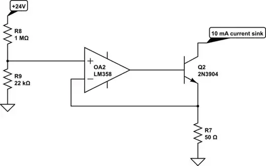
I used OA1 as feedback for adjust pin and OA2 as a buffer, there's a 10 mA load at the output to meet the minimum load requirement of the LM317.

The output voltage of LM317 is now totally dependent on the load on the output. Why? When there's no load output voltage is 9.5V and connecting the non-inverting input of OA2 to any voltage pulls the output of LM317 to 22V and stays there.

Now if I connect any load, voltage will drop depending on the amount of load and it doesn't matter to what voltage the non-inverting pin of OA2 is connected!

How can I control the output of LM317 digitally and have a constant voltage?

JRE
  • 67,678
  • 8
  • 104
  • 179
ElectronSurf
  • 2,185
  • 3
  • 24
  • 61
  • 3
    OA1 is connected in the wrong polarity; swap the connection to the (+) and (-) terminals. – Whit3rd Nov 11 '19 at 11:17
  • @Whit3rd That solved the problem! Thanks you. – ElectronSurf Nov 11 '19 at 11:24
  • 1
    @Whit3rd Can you make it an answer? – winny Nov 11 '19 at 11:28
  • 1
    @Whit3rd If you did write an answer please suggest a good stable 10mA load for this circuit, Thanks again. – ElectronSurf Nov 11 '19 at 11:39
  • 2
    @Hamed, the constant-current 10mA load is another question entirely. You may want to look around this site, I'm pretty sure it's been covered here, look around for "constant current sink", like [this question](https://electronics.stackexchange.com/questions/230701/cheap-low-quality-constant-current-sink-over-wide-voltage-range) – anrieff Nov 11 '19 at 12:02

1 Answers1

1

The main issue, is that OA1 is connected in the wrong polarity; swap the connection to the (+) and (-) terminals.

The use of a resistor to pull-down the output (in order to correctly bias the LM317) is problematic because it's output-value dependent.

Instead, you can use the OA2 section to regulate current with a transistor, taking the +24V power as a rough reference voltage value, thus:

schematic

simulate this circuit – Schematic created using CircuitLab

This current sink should be constant down to under 1V (and the LM317 can't be driven under 1.2V output, in any case).

If a negative power supply were available, the transistor and an emitter resistor would be the only current-sink components required; just ground the base and connect emitter through the right resistor value to the (-V).

Whit3rd
  • 7,177
  • 22
  • 27