1

I found a fat AC doorbell lying in my garage taking dust, and I want to use it as an additional acoustic signal for my DIY home alarm. As per printed specs on its downside it accepts 8-12V AC, and sure enough inside there's the very simple solenoid magnet pulling a small plunger against the outside metal cup.

I know I could just use a simple AC transformer, bypassing the internal full bridge rectifier to get a low-voltage AC output, but my requirement is avoiding the AC mains completely, and only using the 12V line which already powers all my burglar alarm hardware.

I was surprised there isn't, from the usual low-cost suppliers, a simple dc-ac inverter that won't raise the output to 220V, they are all 12V DC - 220V AC inverters with at least 100W output, that are bulky, overloaded and especially expensive for what I need.

I thought I could use a 50Hz oscillator based on a NE555 chip (2$ shipped or something like that), but they can withstand a max of 200mA output current and I'm not sure it's enough for my doorbell. I could have the oscillator control a relay to give power to the doorbell, but I'm not sure it would output a nice "electric bell" effect, and that's also too convoluted for me.

Can you suggest an extremely simple, extremely cheap way to feed something that resembles "8-12V AC" to the doorbell by using 12V DC as source?

ephestione
  • 40
  • 6
  • 1
    Have you considered just supplying it with 12V DC? Solenoids don't _require_ AC. – JYelton Nov 08 '19 at 20:01
  • Is the AC voltage connected directly to the solenoid hitting the "bell"? (I love door bell projects!) – Jakob Halskov Nov 08 '19 at 20:02
  • 1
    Chances are very high that it'll work just fine from 12VDC, as long as you take care of the inductive spike when you let off the switch. Try it, and report back here -- then you can answer your own question! – TimWescott Nov 08 '19 at 20:09
  • Is this doorbell thing that you want to use as an alarm something that makes a simple "ding ding" sound? Or does it ring as long as the button is held down? – jonk Nov 08 '19 at 21:02
  • By the way, in olden days they just used a relay wired to turn itself off when it moved after being turned on by DC applied to its coil. This immediately chopped up DC into AC and was used for transformers in radios. You could adjust the weights inside for the frequency you wanted, too. Have you considered something like that? – jonk Nov 08 '19 at 21:11
  • With DC it would surely ring... once :) Just one DINNNNNG and then stop, while what I'm after is the continuous,and especially fast "dingdingdingdingdingding" that the AC will get me. I undertand what @jonk says, having the plunger open the circuit when hits so it will hit again later, but I wouldn't be able to easily make it do so – ephestione Nov 09 '19 at 07:37
  • @ephestione It's really easy. You can do it with almost any relay. But they used to make them in massive quantities (for automobile use.) Here's [a picture of one](https://i.stack.imgur.com/xUcyG.png). – jonk Nov 09 '19 at 08:11
  • @jonk surely I could build a makeshift switch where I don't use a proper relay but rather a simple NC switch (a momentary NO switch that is pressed by the plunger at rest?) that gets open when the plunger hits. I suppose tho that the frequency of the DINGing wouldn't be so thrilling. I'm looking after the "school hour ending" bell if you know what I mean – ephestione Nov 09 '19 at 14:56
  • I kind of abandoned this project after realizing it is all but a good idea to use it as a "siren"... I tested the power draw and sound output, it's about 3A average at 12V, with approximately 100dB sound power, while cheapo chinese sirens output 110-120dB (depending on the model) while absorbing from 200 to 350mA :-| – ephestione Nov 09 '19 at 17:35
  • @ephestione Okay. Got it. So it's dropped. – jonk Nov 09 '19 at 19:04
  • @jonk not exatly, I would still like to get an answer :) someone else might be looking for it or I might want to still use this electric bell in the future for something else – ephestione Nov 09 '19 at 19:18
  • @ephestione Added, then. Hopefully, it makes some sense to you. – jonk Nov 09 '19 at 20:31

1 Answers1

1

The following schematic is a kind of adaptation of the old vibrating reed relays that were used "back in the day" when someone wanted to place a HAM radio in their car trunk. (They need hundreds of volts for the plate voltage of their vacuum tubes and a \$6\:\text{V}\$ or \$12\:\text{V}\$ car battery just wasn't, by itself, up to it.)

schematic

simulate this circuit – Schematic created using CircuitLab

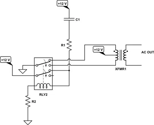
\$R_2\$ is fairly simple. It may be zero Ohms or it may be some other value. But having it allows you to adjust the coil current in the relay coil so that you get just want you want. I recommend keeping it and then adjusting it until you get a vibration frequency you want. This may mean selecting a relay specified for less than \$12\:\text{V}\$ coil voltage. Regardless, the coil voltage and this resistor are your means of getting the relay frequency you want. (You could also include a capacitor, but I don't recommend playing that game right now.)

\$R_1\$ and \$C_1\$ make up want is called a "snubber." These are needed to damp out the coil energy when it is disengaged from power and its magnetic field energy needs to be dissipated. (\$R_2\$ participates in this snubbing, too.) Again, designing those two parts means knowing a lot more about the relay coil. So for now, I'm merely pointing out that you need them. (A diode or a diode and zener might be another approach to try out.) Aside from snubbing, they may also have an impact on the frequency and robust behavior (or lack of it) of the overall circuit. So the process of coordinating the relay coil's mechanical mass and natural frequency details, coil inductance and internal resistance details, and the two resistors and the one capacitor needs awareness and probably some work to get into the right balance. (This is part of why I probably would not use a diode for energy dissipation. I want an additional degree of freedom for tweaking things.)

Other than that, I think you can see that a small transformer with a center tap is used. At the beginning (say, \$t=0\$), the relay coil is directly powered by the power supply with possible current limiting added by \$R_2\$. But also, one half of the transformer is also powered (the upper half, in this diagram.) The relay pulls at the switches and they move towards the other position. (You will need to make sure it reaches that new position due to enough momentum to get there.) Make sure you get a relay that supports switches that "break before make." When the new switch position is hit, the alternate (lower) side of transformer gets actively powered while the relay coil itself loses direct access to the power supply rail and so it loses power and also its magnetic field collapses. That field energy is then dissipated through \$R_1\$, \$R_2\$, and \$C_1\$. When the relay returns to its prior position, due to the loss of its magnetic field, the process starts over.

The upshot is that you've created a "mechanical switching" inverter supply and the output of the transformer will be a useful AC voltage.

The faster you can get the relay to operate (low mass is good), the smaller the transformer can usefully be. Faster is much better if you want "small." However, of course, that has an impact on the relay life, too. And, of course, you need to take into account your alarm that may be attached at the other end. Too fast and the alarm doesn't perform well for you. So the whole thing is a balancing act, of sorts. But it has the advantage that you don't have to be a mathematical genius to tinker with it until you get what you need.

If you can actually find a vibrating reed relay to use, so much the better. But they are antiques now and probably cost money. And they were "big" back then. So with modern, tiny relays there is an opportunity for a smaller "system."

Here's a picture of the inside of one of the old vibrating reed relays:

enter image description here

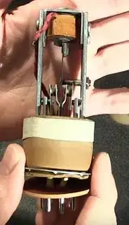
You can see a weight or mass near the top of the thin, vertical "reed" which is used to adjust the vibrating frequency (add or subtract mass.) You may also note the screw that enters from the right side and touches the reed from the right. That formed one of the switches and you could also adjust the screw (press harder or less hard on the reed when it wasn't operating) to also adjust the frequency. The mass and the screw have differing impacts, so making this thing work "properly" involved adjusting both the mass and the screw to get "perfect" behavior.

[The above picture comes from a video produced from "Mr. Carlson's Lab", which you can view in its entirety here.]

jonk
  • 77,059
  • 6
  • 73
  • 185
  • This was a interesting AND complicated read for someone like me whose head these concepts fly over, and now at least I know it's not a project I can tackle for the time being. I mean, I can surely source the parts and begin soldering, yet I like to have solid understanding of what I'm going to do when currents are involved, and probably I need to read this some more times plus look over more information first – ephestione Nov 11 '19 at 11:25
  • @ephestione It isn't too complicated. Actually, if you bought a small DPDT relay, you could wire up something really quick and just see what happens. Without the transformer, it will just clack away really fast. With the transformer added, you'll see AC voltages appear. There is a very good video about all this, sadly behind a paywall. – jonk Nov 11 '19 at 11:46
  • I just ordered a few of them just to play about, in a couple months I should get them :D – ephestione Nov 12 '19 at 20:27
  • @ephestione Have fun. This is something you can easily play with and get working. Just start with getting the relay to vibrate well. Don't add the transformer until you are satisfied with the relay behavior. Those resistors and the capacitor can be adjusted. You'd like the relay to spend about as much time on one side as on the other, when switching. If you have a scope, you can monitor this while you "tweak" things. When you add the transformer, uncover the relay, turn out the lights, and you may see small sparks fly across the moving contacts. – jonk Nov 12 '19 at 21:24
  • @ephestione I found the video on youtube. [See here](https://youtu.be/bROZ4hGisgM?t=515). I've put you at about the right start. Just follow along from there. You will see the author go into GREAT DETAIL about these vibrating reed relays. VERY MUCH WORTH WATCHING. It's also a lot of fun to watch him repair the unit so that it works correctly. Best wishes!! – jonk Nov 13 '19 at 06:49
  • wow, thank you for the caring attitude, I very much appreciate it, that's all good karma for you – ephestione Nov 14 '19 at 21:28