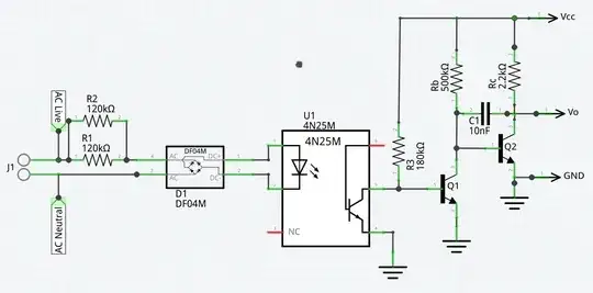
I am a hobbyist working on a project that requires a linear ramp generator (0VDC to 5VDC @ 120Hz) that is triggered by an external pulse. The requirement for the external pulse is so that the ramp waveform lines up with the zero crossing of the 60Hz AC power that I am attempting to "dim" with triacs (so it can potentially be used with inductive loads). The output of the ramp generator (Vo) will go to a comparator that will also look at the voltage of a voltage divider controlled by a potentiometer to fire the triacs for the appropriate amount of time during each half cycle of the 60Hz AC. The schematic below shows what I have come up with so far. I am considering referencing Q1 and Q2 to -5VDC instead of ground and using a diode clamp from GND to Vo in order to keep the output waveform in the more linear region of the RC discharge curve. I have narrowed the width of the pulse trigger at the base of Q1 to 420usec (5% of 1/120Hz), which would be acceptable, but would like to see it narrowed to 0.1% of the period if possible (8.33usec). Possibly some sort of high pass filter? Trying to narrow it more by further increasing the value of R3 causes circuit instability. Q1 and Q2 are currently both 2N4401TF (small signal transistor) devices.
Am I on the right track here, or is there a much simpler and cheaper way of going about what I am trying to do?
