1

During testing, a capacitor was found to cause an intermittent failure - going short circuit when heated.

The capacitor style is a through hole, radial lead, CECC rated 68nF MLCC. Our supplier makes these in small batches, so we assume they buy in SMT capacitors, solder leads + encapsulate them. It is not known if this is an automated process.

Equivalent Style

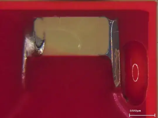
During sectioning, it is shown that there are significant cracks across the surface. Xray reveals these cracks are deep.

Question: What conclusions can be drawn from this analysis?
enter image description here enter image description here

MIL-SPEC
  • 1,088
  • 6
  • 18
  • 1
    Was this test performed before or after assembly to a board? if after, what process was used for soldering? – Peter Smith Oct 31 '19 at 10:10
  • 1
    Can you explain why you believe this: *we assume they buy in SMT capacitors, solder leads + encapsulate them.* in other words, are there some special reasons why this is done? – Andy aka Oct 31 '19 at 10:16
  • @PeterSmith These capacitors have been removed from equipment that failed board level testing. We wave solder them. – MIL-SPEC Oct 31 '19 at 10:25
  • @Andyaka Well, to continue the assumption, this would be to create THT versions of high-reliability components by using another company's chip capacitor that is rated to CECC specs. Look at the sectioning image - thats a surface mount cap with wires soldered on. There is even flux residue on the bottom of the left terminal. I'm hesistant to name the company here. – MIL-SPEC Oct 31 '19 at 10:28
  • So, what is the reason for not using a standard part made by some reputable (hopefully) company who are well-versed in making THT leaded capacitors? Is it an odd value or uncommon voltage rating? – Andy aka Oct 31 '19 at 10:33
  • 2
    My opinion: SMD capacitors cannot handle much mechanical and temperature stress. The construction that is made does not seem to provide much stress relief from stress coming in via the wires. SMD caps are designed to be mounted on a PCB, that's not the case here. Why not simply use leaded capacitors? – Bimpelrekkie Oct 31 '19 at 10:37
  • We were not aware of the construction before this analysis. The issue has been sourcing CECC 30701-007 rated components and this well known (at least in my industry) manufacturer supplies these components in various hard to find specifications, dielectrics etc. We support legacy products where changing components is a lengthy and cumbersome process, taking actual months. – MIL-SPEC Oct 31 '19 at 10:51
  • 2
    In the past I have had capacitors delaminate and crack in wave soldering because the *local* temperature was far too high; this *can* be due to the amount of copper in the area. If you are seeing failed devices in a specific area of the PCB this may well be the cause of the issue. – Peter Smith Oct 31 '19 at 11:21
  • @PeterSmith We initially suspected an issue with the wave solder temperatures but heat strip tests showed the capacitor in question never exceeds 70c. Also we have not seen this type of failure before, and this process has been consistent for hundreds of boards. From the damage, it looks mechanical. – MIL-SPEC Oct 31 '19 at 17:15

0 Answers0