0

schematic

simulate this circuit – Schematic created using CircuitLab

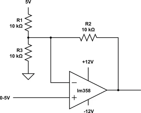
The formula Vout = Vin * (1 + R2 / R1) is not valid for this case? because for example I'm feeding 2.567V to non-inverting input and getting 2.976V at the output! I'm certainly doing something wrong somewhere...

How to calculate the output of non-inverting amplifier with negative supply rail?


Edit:

What I want from this configuration is to provide -1.25V to LM338 linear regulator to get 0V at its output, James mentioned in his answer to remove R3 from the first schematic and I did that with minor gain modification:

schematic

simulate this circuit

At 1V the output is 0V and when non-inverting input is 0V the output of opamp is at 1/4 of Vref 1.250V.

  • What's this configuration name? is it an inverting configuration?

  • What's the equation to calculate output?

ElectronSurf
  • 2,185
  • 3
  • 24
  • 61
  • The equation you give is valid for a non-inverting amplifier, but your circuit isn't just a non-inverting amplifier. You are adding an offset of some kind with R1 and R3. – JRE Oct 25 '19 at 11:04
  • @JRE what's the correct equation for this example? – ElectronSurf Oct 25 '19 at 11:06
  • Not sure. I'm just sure that the one you've got doesn't match your circuit. Do you need to add that offset? – JRE Oct 25 '19 at 11:09
  • @JRE I'm trying to get **~** -/+5V at the output with only 0-5V input, added the offset and gain of two but have no idea what the equation is... – ElectronSurf Oct 25 '19 at 11:11
  • 1
    Ok. Then we can both wait for someone more knowledgeable to wander in and explain how best to do what you need done. – JRE Oct 25 '19 at 11:13
  • The negative supply rail doesn't alter the behaviour or equations, just allows it to output negative voltages as well as positive ones. – Finbarr Oct 25 '19 at 11:43
  • What are you trying to achieve anyway? To design a non-inverting amp with offset, or to understand the behaviour of this particular circuit? – Finbarr Oct 25 '19 at 11:45
  • @Finbarr trying to make an output of -5V to +5V with opamp from DAC 0-5V output. and I'm a beginner in electronics. – ElectronSurf Oct 25 '19 at 12:02
  • Possible duplicate of [Level shifting a +/- 2.5V signal to 0 - 5V](https://electronics.stackexchange.com/questions/37095/level-shifting-a-2-5v-signal-to-0-5v) – Finbarr Oct 25 '19 at 12:17

3 Answers3

2

Remove R3 and it'll work as you require.

Edit

When input is 0V, the output is -1.25V. Perhaps missing the minus sign off was just a typo. Also assuming Vref is still +5V and that's a dash not a minus sign.

That is a non-inverting amplifier, the input voltage goes into the non-inverting input. If the input is +ve with respect to Vref then the output is +ve with respect to Vref. If the input is -ve with respect to Vref then the output is -ve with respect to Vref. It's a more rarely seen non-inverting amplifier because Vref isn't at 0V.

You'd probably have trouble finding a 4k resistor. I'd recommend R1=12k and R2=3k to get your 4X ratio. (E24 series).

Equation is:-

Vout = (Vin - Vref)(R2/R1) + Vin

where in your case Vref =+5V

You seem to perhaps be designing a variable voltage power supply, are you using a PIC to control it?

1

Since this looks like a good homework problem I will only give you a general method.

First, you need to know the voltage at the non-inverting input. Since it is variable in this case let's call it \$V_S\$.

Second, you need to determine how much current flows from R1 and R3 toward the inverting input. The inverting input must be at the same voltage as the non-inverting input, which is \$V_S\$. So you have a simple circuit problem, with the 5V source, R1, R3, and a virtual short to \$V_S\$. Analyze the circuit to find the current flowing toward the virtual short to \$V_S\$, expressed as a function of \$V_S\$ and the values of R1 and R3.

Third, you know that the current flowing toward the virtual short does not actually flow into the inverting input...there is no current into the inverting input for an ideal op amp. So, that same exact current must flow to the output through R2. Set up a simple KVL problem with the virtual source of \$V_S\$ at the inverting input, R2, and \$V_{OUT}\$. The only unknown here is \$V_{OUT}\$, so you can use a little algebra to find the formula for \$V_{OUT}\$ as a function of \$V_S\$ and the resistor values.

Elliot Alderson
  • 31,192
  • 5
  • 29
  • 67
1

Superposition is your friend here. Instead of trying to analyze the circuit all at once (though that certainly is possible), break it into 2 familiar problems:

1) A non-inverting amplifier with \$G = 1 + \frac{R_2}{R_1||R_3}\$

2) An inverting amplifier with \$G = -\frac{R_2}{R_1}\$

Then the total output is the sum of the individual outputs. The negative supply rail has nothing directly to do with the output, except that a negative rail is required to get a negative output. However, if all you're trying to do is get -1.25V at the output, just remove R3, ground the non-inverting input, and apply 1.25V to the inverting input.

pr871
  • 1,167
  • 10
  • 23