0

I have a problem with perfboard, every time I made a circuit which works flawlessly in breadboard, doesn't work on perfboard. Is it because of soldering distance or am I doing something wrong?

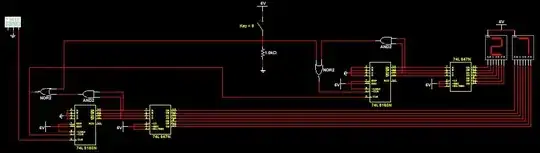
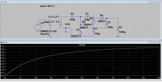
All circuits are 5-12V and low current (200mA max). First one is 7 segment display, second one pwm motor control, last one Ne555 frequency generator. Display circuit's problem is display randomly flickers segment. PWM's problem is MOSFET randomly opening or closing (and heats up). NE555 problem is output is always on even NE555 removed.

It seems like solder or perfboard causing the voltage jump (somehow) but I checked several times and multimeter shows no connectivity, I tried to clean the paste and clean the space between solders but still no luck. Some of my circuits to show the problem:

enter image description here

enter image description here

enter image description here

enter image description here

JYelton
  • 32,302
  • 33
  • 134
  • 249
Mordecai
  • 409
  • 2
  • 7
  • 15
  • 3
    You're probably just making errors when assembling. I find my chances of getting a PCB to work properly are always much lower on a protoboard when I'm basically wiring "on-the-fly" than on a custom PCB. There's just way more that can go wrong. – DKNguyen Oct 18 '19 at 21:54
  • I'm writing a schematic before I solder something , because I always get confused where to solder but I checked several times no mistakes or component damage (all components works when I removed them from perfboard – Mordecai Oct 18 '19 at 21:57
  • @Mordecai I know, but now you're juggling multiple tasks while soldering the board and the number of things that can go wrong still hasn't changed. I actually don't use solder bridges like yours for that reason (harder to fix things and spot errors), but it's also a pain because now you're working with little wires and junk and it's a lot more effort to make it look neat. Enough that I don't really bother trying to. – DKNguyen Oct 18 '19 at 21:58
  • 2
    Those are some neat, but large soldering bridges. You might consider using less solder and smaller gauge wiring to connect things. That would reduce the chance of having unintentional bridges. – JYelton Oct 18 '19 at 22:00
  • 2
    Switch to stripboard such as Veroboard. See my answer to https://electronics.stackexchange.com/questions/395053/is-it-normal-common-to-use-this-way-of-connecting-point-to-point-wire/395058#395058. That way you only need a quick solder spot on each component leg or pin. – Transistor Oct 18 '19 at 22:00
  • @Transistor What's difference between stripboard, veroboard or perfboard ? All looks same for me. About punctuation my phone does it automatically but I will fix that, like this sentence ? – Mordecai Oct 18 '19 at 22:04
  • 1
    They don't really have exact names. Veroboard is more of a brand name. Stripboard has copper trips. I consider perfboard (perforated board) to just have holes and not even copper pads, but some people might include copper pads. Perfboard definitely doesn't have connections between holes. I call a protoboard (prototyping board) anything generic board that you solder that isn't a custom PCB. – DKNguyen Oct 18 '19 at 22:09
  • So about answer , I should use cables to connect components ? Still don't understand why it's causing voltage to jump ? Is it because of copper pads ? – Mordecai Oct 18 '19 at 22:09
  • 1
    Related, maybe helpful: https://electronics.stackexchange.com/q/2215/2028, https://electronics.stackexchange.com/q/176233/2028, and https://electronics.stackexchange.com/q/55236/2028 – JYelton Oct 18 '19 at 22:10
  • 1
    @Mordecai Using wires does help eliminate shorts along the length. It mainly means just means I can cleanly remove or change an entire connection if I have to and I look for bad connections at the wiring point, not along the entire length. You can also jump over things however you want. But now you have to strip the ends of the wire and manipulate them and they can sometimes not go the way you want and make a bad connection. It also won't look as neat unless you get really really good at it. You might like a wiring pen but I find magnet wire to be a pain to solder through even if no strip. – DKNguyen Oct 18 '19 at 22:10
  • I remember someone said in AC circuits sharp edges causing to small arcs . If I remember correctly it's because of ac is flowing outside of copper (like surface) not inside of copper. Like electrons can't turn 90° angle and flow into air – Mordecai Oct 18 '19 at 22:14
  • Wow , thanks for all the comments . I made exactly same circuit with cardboard and it worked flawlessly . – Mordecai Oct 18 '19 at 23:35
  • 1
    As others have said, stripboard (eg Veroboard) with rows of Copper, is (I find) FAR easier to use than boards with many isolated pads. The opportunities for error and shorts are far greater with perf board. Strip board MAY not be quite as space efficient as an immaculately executed perf board - but ever achieving that on a perf board is very very hard. – Russell McMahon Oct 19 '19 at 00:05
  • 1
    @Mordecai - "*Still don't understand why it's causing voltage to jump ?*" Using a perfboard does not cause "voltage to jump". Your guess about that concept is incorrect. There are some possible causes for your problems and I was part-way through writing an answer earlier. However when you accepted the duplicate closure option, it closed this question & I couldn't submit my answer here. Hopefully the answers in the duplicate will help you. Just forget any idea that using perboard causes "voltage to jump" - it does not. Your problems are construction-related problems. Sincere good luck! – SamGibson Oct 19 '19 at 00:15
  • I made same circuit and it worked flawlessly so if you're meaning some other kind of construction related problem which caused by perfboard, it's possible but I didn't make any mistakes about connection. – Mordecai Oct 19 '19 at 00:25
  • @Mordecai - "*if you're meaning some other kind of construction related problem which caused by perfboard, it's possible*" Yes, but not caused *by* perfboard - instead caused by the construction on perfboard shown in the photos. (For example, in the [first photo](https://i.stack.imgur.com/XV2f7.jpg), there is so much flux residue it's impossible to visually check for solder bridges & some solder joints appear incomplete.) Millions of projects must have been built successfully on perfboard. So, to avoid you wasting your time, forget any concept of perfboard causing "voltage to jump". Good luck! – SamGibson Oct 19 '19 at 00:59
  • I would use much less solder, then you have fewer places for unwanted solder bridges to hide. Instead of staking the wire to every pad, just run the wire straight along the pads and use a solder blob at each end to hold it, and a blob where you connect to it. – Neil_UK Oct 19 '19 at 04:39
  • "*What's difference between stripboard, veroboard or perfboard?*" The difference is that you don't need solder bridges between all the components. The bridges require much more heat, risk damaging the components and risk creating short-circuits. It's also much easier to fix errors or make changes. – Transistor Oct 19 '19 at 08:19

0 Answers0