3

I'm trying out the IP5306 (The datasheet is in Chinese, I used the "document" feature of Google Translate to translate it).

Here is my schematic:

enter image description here

The IP5306 is a cheap boost chip that is normally used for charging mobile phones. Its typical application involves boosting a lipo to 5V. It also charges the lipo via a micro USB port. I'm using it to power a small portable load (~60-200mA @5V).

SW1 turns on and off a PFET that connects or disconnects the lipo from the IP5306.

I have assembled a few boards and am currently in the verification/debugging phase. At first, the board didn't work at all. This was due to my misinterpretation of part 10 of the translated datasheet, which states "The IP5306 recognizes long and short button operations, and the PIN5 pin is left unconnected when no buttons are pressed".

I thought this meant I could leave pin 5 unconnected and the IC would function normally. Unfortunately, pin 5 (the "key" pin) needs to be pulled down by a short button press (longer than 50ms and shorter than 2 seconds) in order for the device to start up and boost the battery voltage to 5V and provide current to a load. I didn't account for this in my design, and left the key pin disconnected.

I've been trying for hours to think of a way to automate the temporary pulldown action immediately after SW1 connects the battery with the IP5306. I'd really like to add something small and simple (I have resistors, capacitors, inductors, transistors, FETS) to the design without redoing the whole thing. The pulldown action must be longer than 50ms and shorter than 2 seconds. Any ideas???

Current progress:
schematic

simulate this circuit – Schematic created using CircuitLab

Sean Dever
  • 301
  • 3
  • 9
Payton Grenich
  • 491
  • 4
  • 16

2 Answers2

2

This may work:

POSSIBLY a capacitor to ground and a very large value pullup to half supply will work. It may be that an eg 1MOhm to Vin is seen as an open - or a 1M/1M divider so the pin sits at 2.5V or so.
THEN a cap to ground will start the pin at 0V and then charge the cap.
It MAY be that there is an in IC pullup to some OC value so only a cap is needed.

This will work:

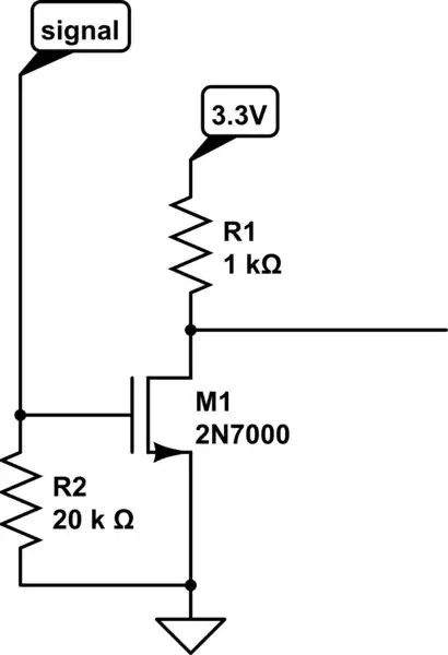
A basic timer can be made with an eg NChannel MOSFET a cap and a resistor. I've added a 10k resistor from FET drain to pin 5 due to updated user information.

On power up cap pulls FET on,
FET grounds pin 5.
Resistor discharges cap and FET turns off.

schematic

simulate this circuit – Schematic created using CircuitLab
Russell McMahon
  • 147,325
  • 18
  • 210
  • 386
  • Hi Russell, thanks for the response. I added a schematic to my original post of what I think you're describing. I replaced the 5V net with the battery voltage since the boost hasn't turned on so 5V isn't available yet. I don't think what I drew will work since when SW1 is flipped, the battery voltage will prevent C1 from discharging through R1. Did I draw the schematic wrong? – Payton Grenich Oct 08 '19 at 21:47
  • @PaytonGrenich I said "Cap from 5V to gate". You have cap from gnd to gate. My way when 5V turns on Vcap is the same on both plates and cap cannot change V instantaneously so gate is pulled to 5V by psu turn on. resistor then discharges it. – Russell McMahon Oct 09 '19 at 01:19
  • My mistake - schematic edited. I think there is still a problem - in order for the 5V signal to appear on the capacitor, pin 5 must first be pulled down then left floating (within 2 seconds). I think this would work if 5V appeared when pin 5 were pulled down but as it is pin 5 will not be disconnected from ground. – Payton Grenich Oct 09 '19 at 22:14
  • @PaytonGrenich You need to read through my answer (and indeed any answer that is not wholly obvious to you) carefully and ensure you try what it says. In the "may work" section I said that a pullup to half supply MAY work to simulate an open (at some value of "high" it WILL look like a short circuit. I noted that there MAY be an internal pullup (which will swamp an external R at some value of R). In the "will work" section I have MOSFET that turns off and goes OC. Why is that not suitable? | – Russell McMahon Oct 10 '19 at 04:40
1

Try about 47uF in series with 10K from pin 5 to ground. If that works, try from about 10uF to 220uF. Pick something near the center of the range that works.

The diode is optional and may help prevent it from not starting if power is interrupted briefly.

schematic

simulate this circuit – Schematic created using CircuitLab
Spehro Pefhany
  • 376,485
  • 21
  • 320
  • 842