I'm doing an LED project with a 36V Cree CXB3590 COB LED that I intend to underpower to experiment with efficiency and learn about boost converter design. I've made a 5uH inductor with 14 gauge magnet wire wound onto a T50 toroidal yellow/white(iron powder) core. I plan to use a 555 clock circuit and a 555 pulse generator with a horrible oscilloscope to determine the maximum pulse length for the inductor core and then experiment with frequency to compare total light output from the CXB3590 at different power levels to the output from single LEDs such as an XP-G or XR-E at the same power level. I'll be using PWM with a frequency limit ~1Mhz due to the iron powder core inductor. The large wire on the inductor and a decent MOSFET are intended to keep resistive losses as low as possible, hopefully negligible.
Because the CXB3590 is capable of using much more power than the boost converter circuit is likely to provide, I'm hoping to use it as both output diode and load, making the assumption that with each pulse the inductor will drive voltage up to the on voltage of the LED (~33-34V) and when that voltage is reached because the LED's effective resistance will become extremely low, it will not rise significantly higher as the inductor dumps its stored energy.
I'm hoping that this will result in the LED operating in a favorable efficiency band, operating in discontinuous mode and at close to the lowest voltage that will allow it to dissipate the power being pumped into it.
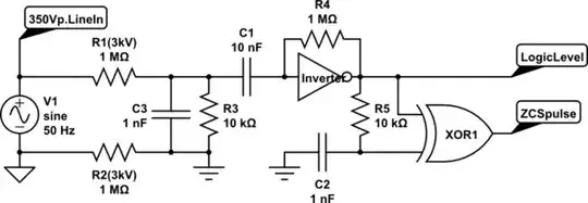
simulate this circuit – Schematic created using CircuitLab
So my question is this: For what reason(s) I would benefit from using the topology shown on the right, such as the inclusion of a capacitor helping clamp down the voltage the LED sees? the CXB3590 is rated at 86.4W, so at the ~3-10W I intend to operate it at, as I mention above it will likely operate discontinuously.