2

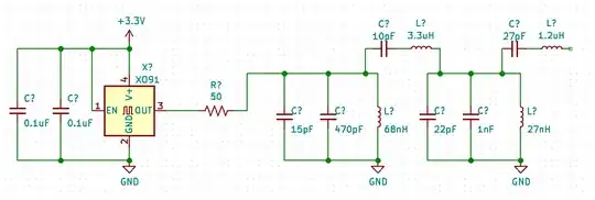
I'm drawing a schematic for my DIY project, a RF mixer, it has a local oscillator followed by a bandpass filter, a voltage divider, eventually the signal is fed into a mixer.

Unfortunately, even before I manage to finish the LO port, the signal path on the drawing becomes very long ("snake syndrome?"). The mixer is supposed to be the center. I expect it to be even more difficult to manage, as the RF port and IF port would also have their own impedance matching and low-pass filter, both will be long snakes. It will make the schematic very unbalanced.

I know hierarchical schematic is a solution: you show all blocking blocks as blackboxes, and then "expand" each blackbox separately. But there should be a way to achieve the same result in a non-hierarchical way. What is the industry standard to show the long signal paths in a reasonable way?

LO:

Snake

Overview (RF and IF would also be snakes when finished):
Overview

比尔盖子
  • 6,064
  • 2
  • 24
  • 51
  • 1
    It's an art. Good logical layout with minimum of "broken wires" is the easiest to read. [Rules-and-guidelines-for-drawing-good-schematics](https://electronics.stackexchange.com/questions/28251/rules-and-guidelines-for-drawing-good-schematics) is a good place to start. – Transistor Sep 23 '19 at 09:17
  • Place LO chain at top, RF/mixer in middle, IF/filtering at bottom – analogsystemsrf Sep 23 '19 at 09:44
  • 1
    Where long schematic lines become confusing. assign a net label / net name on each end of the 'split' net. – Peter Smith Sep 23 '19 at 10:20

1 Answers1

2

The question is still open for suggestions. Meanwhile, I've spent some time attempting to rearrange the diagram, and I identified three modifications and the schematic is significantly better now.

1. Increase the Width of the Blocks

Do not put wires directly to the points of connection on the symbol. Use some vertical wires to create additional widths.

This is a snake.

This is a snake.

But this is better.

Wider schematic makes it less "snake-like"

Similarly, larger versions of components symbols (resistors, capacitors) should be used to fill the gaps, so the dense parts and sparse parts of the diagram can have the same width.

2. Put "Snake Like" blocks vertically.

I've finished the RF parts of the circuit, still a "snake". But when you arrange two "snakes" vertically, narrow "snakes" becomes rectangular.

Narrow "snakes" becomes rectangular.

3. Put Input and Output At the Same Side

Although the rule-of-thumb is routing all signal flow from left-to-right, but putting both the input and output port at the same side avoid irregular shape of the drawing.

Final result

Final result

I think It's not the best possible schematic. But now the readability of the drawing is greatly improved. There may still be rooms of improvements. Any comment?

4. Move the Output to the Right

Following the comments, I moved the output to the right to make sure that the signal always flow from left to right, meanwhile I've put the LDO circuit at the left side to balance the schematics. Not too bad.

Move the Output to the Right, put the LDO circuit to the left side

比尔盖子
  • 6,064
  • 2
  • 24
  • 51
  • 1
    If the mixer output (after transformer coupling) is the output of your circuit, it's better to put it on the right edge of the page, not the left. – The Photon Sep 23 '19 at 14:00
  • I wouldn't recommend putting the input/output on the same side unless you have to (due to symbol constraints). – Caleb Reister Sep 24 '19 at 15:27