8

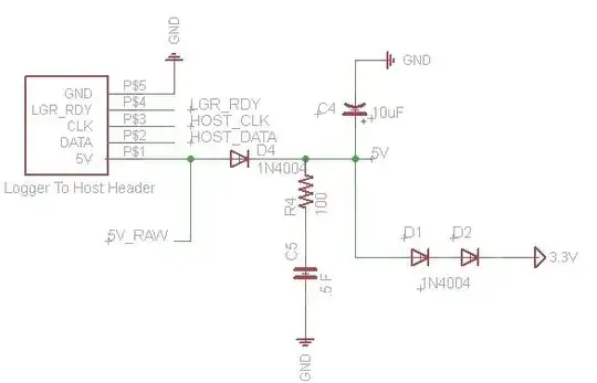
I designing a circuit will store log data to an SD card. The information will be coming form a parent circuit that this one plugs into. The parent circuit will supply 5V to my daughter card. The daughter card uses an MCU that operates at 3.3V so I am just using a couple of diodes to step down the voltage from 5V.

MY CHALLENGE IS: In the event of a power failure, I want the MCU on my daughter card to be able to sense the main power loss and then immediately flush the data from it's RAM to the SD card and then go idle before it shuts down. When writing to an SD card you can cause corruption if you lose power in the middle of a write procedure.

I am thinking about using a big capacitor to just buffer the power for a bit. I know there are some MCU Supervisor IC's out there that would do a really nice job but they are intended for cases where you need to maintain power for days. I just need a second or two at the most. But I do have to be careful about not letting the MCU "flicker" on and off as the capacitor power decreases below the IC's threshold. Does anyone have a schematic or can offer any suggestions of how I should go about this?

Here is what I have so far... (the .5F cap is my power back-up capacitor) alt text

PICyourBrain
  • 3,695
  • 10
  • 41
  • 55
  • 7
    It's a bad idea to use diodes to drop 0.7V, because, well, they don't. If your micro is in standby, they will drop 0.4V-0.6V (so the supply will go from 4.2V to 3.8V - bye bye) and at moderate load they can drop as much as 1V leaving you with only 3V and a possible power reset. – Thomas O Sep 29 '10 at 19:45

3 Answers3

9

Like ajs410 and Thomas say, using diode drops to go from 5V to 3.3V is a Bad Idea™. That's because, despite what you've been told in school, a diode voltage is anything but constant. The 3 diode drops may give you roughly anything between 2.3V and 3.2V, which may or may not be too low for your \$\mu\$C or SD-card.
I would start by replacing D4 with a Schottky type like a BAT54, which has a low leakage current of <1\$\mu\$A typical. This will give us a few hundred mV extra for the buffer capacitor.

Next there's the 3.3V power supply. Use a low ground current LDO, like the Microchip MCP1703, which has a ground current of just 2\$\mu\$A. (The Seiko S-812C40 is a favorite of mine and has even better specs, but seems to have poor availability for low quantities.)

Then you want to detect the loss of your 5V power supply. For this I usually use a MAX809. This will create a low output signal when its input voltage drops below a certain threshold. For a 5V supply threshold voltages of 4.63V, 4.55V and 4.38V are available. The output of the MAX809 goes to your \$\mu\$C's interrupt pin, so that you're immediately warned when the 5V drops, and you can write the buffer to the SD-card without delay.

Now there's only 1 point left: the size of the buffer capacitor. You need to know how much current you're drawing from the 3.3V supply when writing to the SD-card. Let's assume this is 20mA. The capacitor voltage will decrease linearly when a constant current is drawn:

\$ \Delta V = \dfrac{I \times t}{C} \$

or

\$ C = \dfrac{I \times t}{\Delta V} \$

Let's further assume that you need 100ms to write the buffer to the SD-card. Then the only remaining variable is \$ \Delta V\$. We started with 5V minus 1 Schottky diode drop, giving 4.5V. The minimum voltage drop-out for the MCP1703 is 725mV, so we can go down to 4V, and \$ \Delta V\$ = 0.5V. Then

\$ C = \dfrac{20mA \times 100ms}{0.5 V} = 4000 \mu F \$

Now the values I used are rough guesstimates, and you'll have to make the calculation with the correct numbers, but the guesstimate indicates that you may not even need the 0.5F supercap after all, though it gives you a serious safety margin. You would for instance have 10s instead of 100ms to flush the buffer to the SD-card.

(the dropout for the Seiko S812C is only 120mV, so this will double your allowed voltage decrease and hence your available time.)

stevenvh
  • 145,145
  • 21
  • 455
  • 667
  • 1
    What school is telling students that diodes drop a constant 0.7V? Mine started with an I-V graph and the Schockley diode equation. – Kevin Vermeer Aug 30 '11 at 14:23
  • 2
    @Kevin - well it depends what you studied. If your major is philosophy and you take a 20 hour course in electricity you won't get at Shockley, I'm afraid :-). The 0.7V is referred to very often, even for high currents where the forward voltage is often more like 1V. I've been asked here on EE a few times why I calculated with a 2V drop for a bridge rectifier. – stevenvh Aug 30 '11 at 14:28
6

Using diodes to drop voltage? Yuck. Use a 3.3V regulator. It's just the right thing to do. You and/or your customers will be glad you did it.

You have the right idea, generally. Use a huge cap, although .5F might be a bit too huge.

Instead of using a comparator, you could use a voltage divider and run the output into one of the Interrupt-On-Change pins of the PIC. Set up the divider so that the input is a bit above the max Vih when the 5V is active. This has the added bonus of also pulling the 5V down faster once the source is removed.

You could also try using a battery and a power mux. When the 5V goes away, the mux will switch to battery power. http://focus.ti.com/paramsearch/docs/parametricsearch.tsp?family=analog&familyId=422&uiTemplateId=NODE_STRY_PGE_T

ajs410
  • 8,381
  • 5
  • 35
  • 42
  • This reminds me of a Maxim appnote. You can configure some PMOS's up as OR gates, so you can switch to a secondary power supply (e.g. capacitor) when the primary supply is unavailable. – Thomas O Sep 29 '10 at 20:53
  • I decided to go with the circuit shown above except that I replace D1 and D2 with a 3.3Volt regulator. – PICyourBrain Oct 17 '10 at 13:48
3

A solution to this is to use your microcontroller's comparators.

You did not mention what microcontroller you are using, so we can only guess if it actually has comparators on the chip. If your micro has a voltage reference, even better.

But assuming it does, you can set up an interrupt to jump to an ISR. The ISR could switch the clock (if possible) to a low power routine and then shut down. If you're running at a low frequency you may have much longer to perform the save - the tradeoff is however that the save takes more cycles.

Thomas O
  • 31,546
  • 57
  • 182
  • 320
  • I'm using a PIC24FJ64GA002 – PICyourBrain Sep 29 '10 at 19:50
  • Two onboard comparators and a 10 channel ADC. Any of those modules can be used to check the supply voltage is OK. The comparator is better because it can trigger an ISR. I've actually dealt with the PIC24F/H/dsPIC30F/33F series of chips and the interrupts have priorities AFAIK so you can make power fail more important than say ADC conversion done. – Thomas O Sep 29 '10 at 19:54
  • A Schmitt trigger can be built with just a few transistors, a full-blown comparator is not really necessary here. – Kevin Vermeer Sep 29 '10 at 19:56
  • Why use a Schmitt trigger with several transistors which continuously wastes power and costs board space when you have integrated on-die comparators which can be switched off when not needed? (Hint: you could power up the comparator maybe a few hundred times a second to check the supply voltage is in bounds, and save power when not needed.) – Thomas O Sep 29 '10 at 19:58
  • 1
    Rather than using any sort of comparitor, I was just going to look at 5V_RAW on one of my digital inputs and interrupt on any high to low transition. As soon as the interrupt occurs I flush the buffer. But how do I stop the MCU from flickering on an off or is that really a worry? – PICyourBrain Sep 29 '10 at 20:02
  • That will not work. The supply will drop below 3V before a logic transition occurs. Also, the logic inputs will draw current when operating at neither high nor low. – Thomas O Sep 29 '10 at 20:10
  • Ok, I just found in the datasheet that the PIC will operate all the way down to 2.35V when running at 32MHz. – PICyourBrain Sep 29 '10 at 20:36
  • 1
    Yeah - great - but the SD card won't work below 3.3V ±10%. – Thomas O Sep 29 '10 at 20:39
  • hmm yeah I forgot about that. Ok, I think I am going to use a 3.3V regulator, and also see if I can get 12volts from the main board as well as 5V so I can charge up the cap to a much higher voltage. A MCP1702 regulator can take inputs voltages all the way up to 13 volts. – PICyourBrain Sep 30 '10 at 13:12
  • 1
    What's the voltage of your .5F cap? 99% of the time it's less than 6 volts. Careful not to overvolt it; use two in series with some 1 megohm resistors in parallel (to balance the caps.) – Thomas O Sep 30 '10 at 14:09