1

I've built a simple LED sequencer using PIC 18f4550. Outputs are 10 pins on ports C&D. I have now built (soldered) this circuit 3 times and it still only powers on intermittently. I installed a very low current "power on" LED to help troubleshoot. I notice if I touch the chip or certain areas of the board, the circuit works (& power light on). But it intermittently goes out. Almost like there's a loose connection or some capacitive issue. Circuit works fine when the power light is on. Symptoms are the same whether breadboard or soldered. Ideas?

Thanks


please excuse the crudeness of this drawing.
led sequencer for PIC18f4550

Mark
  • 147
  • 2
  • 13
  • 2
    A schematic and/or picture of the circuit will certainly help. – m.Alin Oct 27 '12 at 11:03
  • Did you put 100nF [decoupling capacitors](http://electronics.stackexchange.com/questions/2272/what-is-a-decoupling-capacitor-and-how-do-i-know-if-i-need-one) on each pair of Vdd & Vss pins of the PIC? – m.Alin Oct 27 '12 at 11:07
  • I put 0.1uF. I only put in on one side since they appear to be "common" through the chip. (vdd/vcc exist on other half through PIC). Maybe I should add the other? – Mark Oct 27 '12 at 11:13
  • m.Alin, it's a hand drawn schematic. I'll try to get a digital to upload later. thanks. – Mark Oct 27 '12 at 11:13
  • One cap for the whole PIC should be enough, but I always add one for every pair of Vdd/Vss pins, just to be on the safe side. Also, 100 nF = 0.1 uF – m.Alin Oct 27 '12 at 11:20
  • 1
    One isn't enough! Always decouple each pair! – Leon Heller Oct 27 '12 at 11:32
  • 3
    @LeonHeller You convinced me with your _!!!_ :-) – m.Alin Oct 27 '12 at 11:39
  • How are you handling MCLR? – Dave Tweed Oct 27 '12 at 12:14
  • ok, I put a 4k pullup on MCLR but that didn't fix it. I'm trying to include the schematic. – Mark Oct 27 '12 at 18:20
  • Also, I have tried various configurations for the switch on RB0. I've tried denounced, pullup and both but the same power problem caused me to think those may be contributing so I took them out. When the power is on, this simple ground to RB0 will set off the LEDS as expected. – Mark Oct 27 '12 at 20:15

7 Answers7

5

You probably are missing a pullup on the reset pin (/MCLR)

Jim Paris
  • 2,685
  • 1
  • 12
  • 12
5

"ALL" you need to do is pass the standard sanity checklist and it will work:

Add to these, adjust to suit your perspectives, then print and pin them on your forehead for future reference.

When in trouble, regroup, shorten battle lines, tactically withdraw and concentrate forces on the known areas of attack - aka get the minimum possible system going that does not fail, turn off any code not needed, disable any peripherals etc that you don't need, discard as much as you can of even what you do "need" until you get back to a stable state. THEN advance one change at a time. Be aware that if you make 3 changes a b c in order and a and b work OK and c doesn't then eg a+c may produce a combined fault between them - it may not be just c that is at fault.

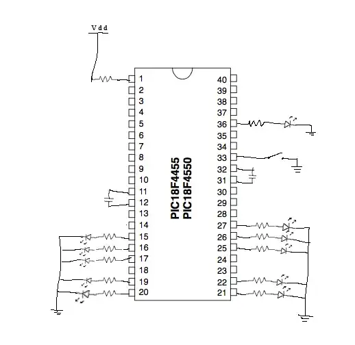
If you do not show what is on every pin on your circuit diagram then you are abusing those who seek to help you and risking fooling yourself*.

If you have set a programmatically or initialisation alterable state on any pin then you need to say what you have done as otherwise you are abusing those who seek to help you and risking fooling yourself*.

Go through the datasheet and confirm that EVERY pin is connected to something valid based on it's logical state. Write down what you have done on the circuit diagram and associated notes.

Describe ALL programmatically or initialisation settable actions you have taken. Datasheet default is assumed for anything you do not say you have set. Stating what the datasheet default is in each case helps people help you and helps you not fool yourself.

Every ground pin should be grounded.

Every Vdd pin should be connected to Vdd.

EVERY input should be connected to a known defined state by a resistance path no higher than what is legally allowed by the data sheet. (Limiting case if not otherwise specified is (offset voltages + bias currents x Resistor path + termination point voltage) all set to the worsts case value and polarity in each case should always place the pin in a valid voltage range. (An internal pullup or pulldown qualifies as a known state as long as you do actually implement it).

Every control pin state must be known and set to a level that specifies a state that is acceptable to you in the overall configuration that you have chosen.

Any operating interrupt generating times must produce known and knowable outcomes.
Known: eg if you have a watchdog timer interrupting operation it must be either prevented from acting by program or hardware action OR it must produce a valid outcome when it acts.
Knowable: If you have a live interrupt it's vector must be set and it must go to valid code whose outcome is acceptable.
Brownout interrupts must be set so power supplies used are valid.

Know what is in data registers - either by bulk setting during startup or by explicit setting that is an unavoidable part of a routine OR know that it does not matter in a given case. If bulk setting at startup be sure this is a valid reason to use the register with confidence subsequently. No ESD conditions.

IC not damaged.

Power supply not spiky / noisy / brownoutable.

"Too hard" and "can't understand"are not conditions understood by a microcontroller, or Murphy. If a peripheral or register has options that you cannot master with confidence then to be certain of outcomes you MUST select some other option for that peripheral or register that you are certain [tm] that you do understand fully. eg if there is a timer that you are not master of, disable it. If you use an interrupt vector, understand it completely. If you don't and cannot or do not want to spend the time DO NOT GUESS.- disable it at this stage until you get the system stable.

ALL the above constitutes a minumum degree of rigour when programming and implementing even the most trivial microcontroller systems. If you cannot or will not do all the above on every occasion then you are not doing the minimum that it takes to do the job properly.

Russell McMahon
  • 147,325
  • 18
  • 210
  • 386
1

Let me try to state the obvious, but sometimes that's what is needed...

Did you connect pins 11, 12, 31, and 32 to power and GND? I know this sounds like a stupid question, but it is not. I have seen chips that don't have power/gnd connected still sort-of work due to leakage and some other stuff on the I/O pins. I have even seen this happen on PCB's that were in volume production! Your schematics shows caps on those pins, but not power/gnd. I figured it was worth mentioning.

  • actually when transferring to the soldered protoboard, I did not connect 31/32. They were connected on the breadboard but still acted flaky there so I went all "minimalist" on the soldered version. It reads vdd/vss on those pins (31/32) from the chip even though only 11/12 are connected. I was wondering why they are spec'd twice if they appear to be in common through inside the chip. – Mark Oct 27 '12 at 22:33
  • "currently" it seems to be working ok, but that doesn't mean it won't still flake out. If it does again, I'll add those back and see. Thanks. – Mark Oct 27 '12 at 22:35
  • @Mark Unless the datasheet says otherwise (this is rare), you must always connect all of the power/gnd pins. Those pins are there for a reason, and you cannot guarantee proper operation without them. This PIC has a max I/O pin output current of 200 mA (for all pins combined), and you probably can't get close to that without connecting all pins. If you are running your 10 LEDs at 20 mA each then you are already at your 200 mA limit. –  Oct 28 '12 at 00:37
1

Whenever you can touch a component and get a desired result its almost always a grounding issue. As stated above make sure all necessary gnd pins are pulled down and use a common ground. Typically when you touch the pcb, chip or board and get the pic functioning its because theres a ground loop issue and your body is acting like a giant mega ohm resistor pulling the circuit to ground and creating a common ground for your circuit.

KP44
  • 126
  • 2
0

The PIC may be entering Low Voltage Programming (LVP) mode. From the PIC18f4550 datasheet:

While programming using Single-Supply Program- ming, VDD is applied to the MCLR/VPP/RE3 pin as in normal execution mode. To enter Programming mode, VDD is applied to the PGM pin.

By default LVP programming is enabled. This means whenever the PGM pin goes high the PIC goes into reset.

An easy way to check if this fixes the problem is to add a pull-down resistor(4.7k - 50k) from the PGM pin on your device to ground. This is pin 38 on the device in your schematic.

The other solution is to clear the LVP bit in the devices configuration registers:

config reg

Don't change the configuration register though if you need to use LVP mode to program your chip!

justing
  • 1,743
  • 13
  • 21
0

There are a lot of great answers here already but I haven't seen anyone mention that there is no oscillator on the schematic. Are you using an internal oscillator? If you do not have an oscillator correctly set up your circuit will not work. Also I agree KP44, the intermittent behavior does sound like a grounding issue.

Brandon Bailey
  • 387
  • 1
  • 14
0

I had a similar issue. In my case /MCLR was pulled high but I had not pulled PGM low. Pulling PGM log fixed my problem

Perhaps this can save someone a bit of time

Andre
  • 267
  • 2
  • 11